3.1Supply current measurement – CMM-Interface
For measurement of the DUT current consumption an external IRS current measurement module (CMM) can be inserted. The module is supplied externally and can be read by means of a synchronous serial channel with LVDS differential digital signalling.
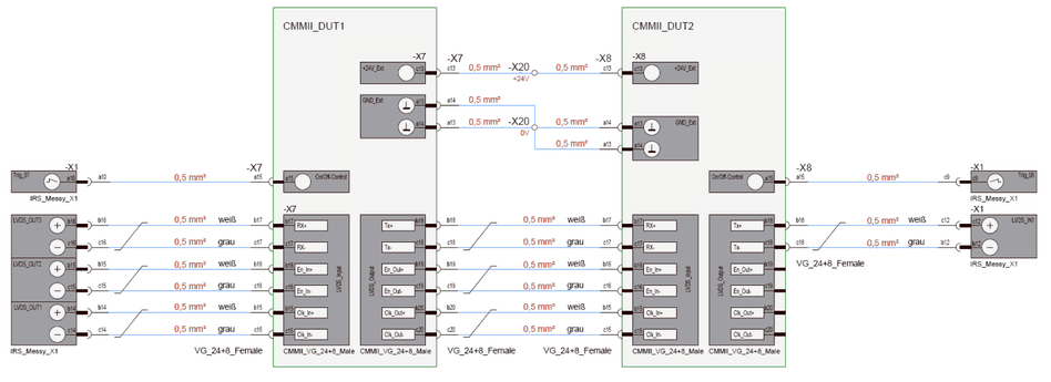
The serial interface is designed in a way to concatenate several CMM’s in a daisy chain type, as illustrated in the following figure, where the test system is actually the LVDS interface, which is available on the base and communication board.

3.1.1Communication protocol
The protocol for reading data of one current measurement module is as follows:

When En_In is asserted, the CMM_II module sends out its current measurement value during the next 32 clock cycles with MSB first. After every 16th clock cycle a pause of approx. 5µs with CLK_In at low level should be left. This delay is used to leave the CMM_II microcontroller time to sort next 16-bit data word. After 32 clock cycles the previously received data word is forwarded by the CMM.
Thus, En_in must be valid for 32 clock cycles, multiplied by number of CMMs in the chain.
The current is returned as 32 Bit unsigned long value in steps of 100nA.
3.1.2Connection Diagram
The connection of the signals is according to the following table:
| MesSy signal | MesSy Pin | CMM_II Signal | CMM_II Pin | Which CMM_II |
|---|---|---|---|---|
| LVDS_Out_3+ | B16 | Rx+ | B17 | First in chain |
| LVDS_Out_3- | C16 | Rx- | C17 | First in chain |
| LVDS_Out_2+ | B15 | En_In+ | B16 | First in chain |
| LVDS_Out_2- | C15 | En_In- | C16 | First in chain |
| LVDS_Out_1+ | B14 | Clk_In+ | B15 | First in chain |
| LVDS_Out_1- | C14 | Clk_In- | C15 | First in chain |
| LVDS_In_1+ | C12 | Tx+ (last CMM) | B18 | Last in chain |
| LVDS_In_1- | B12 | Tx- | C18 | Last in chain |
Following example shows the connection of the communication lines of two CMMs:
3.2Analog or digital output conditioning
For conditioning of digital outputs or using analogue outputs, please refer to document LDSA_MesSy_Guide_HW_V_1_1.docx
3.3External CAN or serial transceivers
For conditioning of digital outputs refer to document LDSA_MesSy_Guide_HW_V_1_1.docx
3.4Analog input conditioning
For conditioning of analog inputs using voltage dividers or load current measurements, please refer to document LDSA_MesSy_Guide_HW_V_1_1.docx, and the data sheet CurrentConverter_8x_Datasheet_V1.0.pdf.
3.5External I2C-interface
MesSys with a base- and communication board of version 1.3 or higher provide an external I²C-interface to connect additional external electronic modules. Any devices compatible to the I²C-specification may be connected to this interface.
At the moment IRS provides two external modules, which can be controlled by this interface:
- 64x Relay board (identical to one Relay subsystem on MesSy’s digital output board)
- 16x analogue output board (output DC voltages 0…20V)
I²C-interface contains two signal lines. The signals are available at MesSy connector X2 according to the table in chapter 2.7.6 with the following functionality. A typical I²C example telegram for controlling digital outputs is shown in chapter 3.4.
| Signal | X2- Pin | Description |
|---|---|---|
| SCL_Ext | B23 | clock line |
| SDA_Ext | C23 | bidirectional data line |
Documents and downloads
Further documents and files for your IRS product are available on myIRS.