1.1SP-400 Mainframe
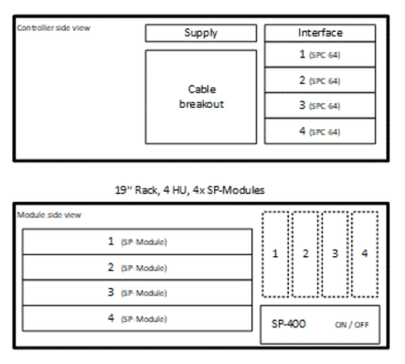
- Mainframe size: 4 HU 19‘‘-Rack
- 4 slots for SP-Modules
- 4 slots for additional eurocards (160x100mm)
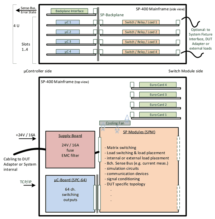
SP Modules (SPM):
- Matrix switching
- Load switching & load placement
- internal or external load placement
- 8ch. Sense Bus (e.g. current meas.)
- simulation circuits
- communication devices
- signal conditioning
- DUT specific topology
- …
Further labels in the schematic:
- µC-Board (SPC-64): 64 ch. switching outputs
- Supply-Board: 24V / 16A fuse, EMC filter
- TCP/IP, +24V / 16A, Sense-Bus, Error State
- Cabling to DUT Adapter or System internal
- Optional: to System Fixture Interface, DUT Adapter or external loads
1.2SP-1200 Mainframe
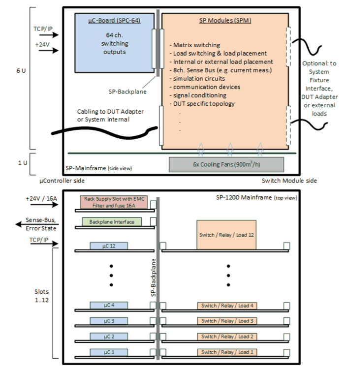
- Mainframe size: 7 HU 19‘‘-Rack
- 12 slots for SP-Modules
- 6 fans for load cooling
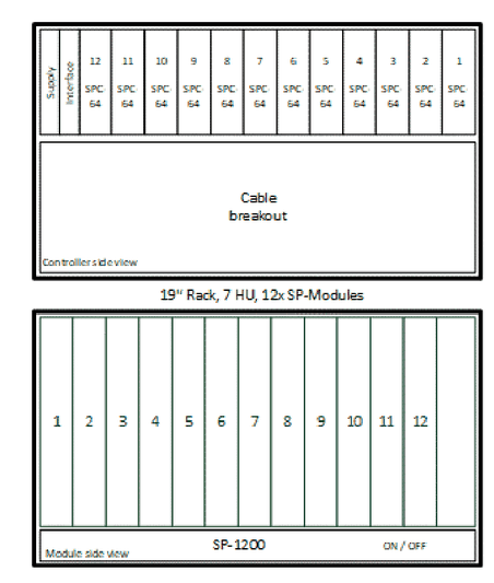
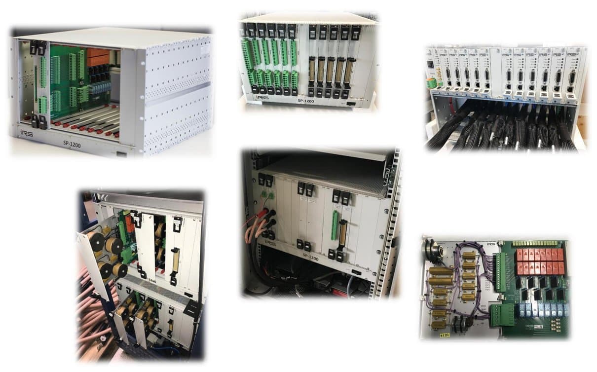
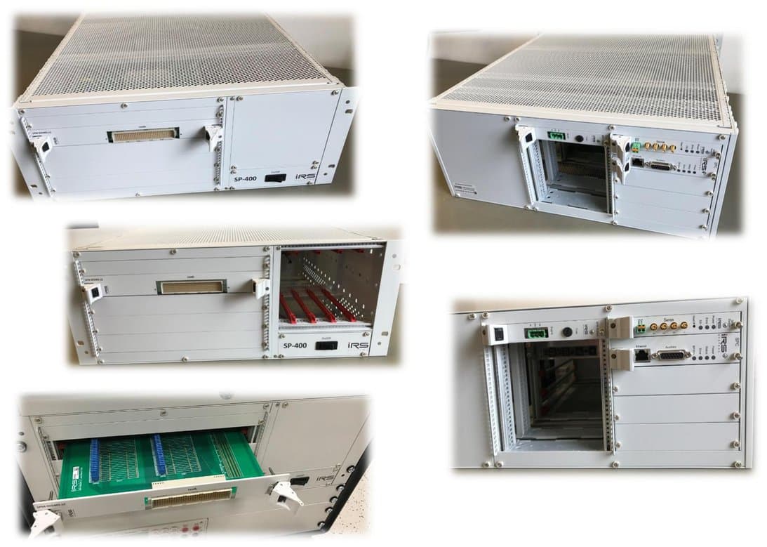
1.2.1Front and rear view
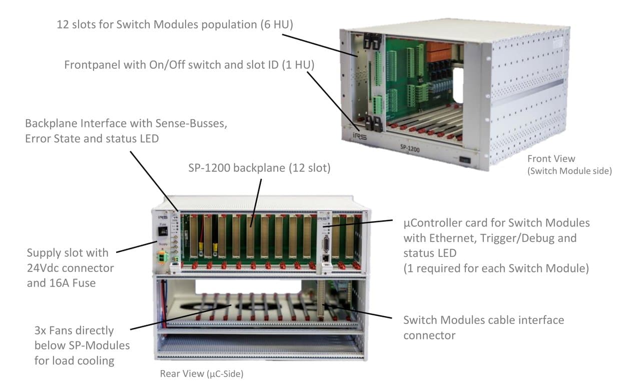
Front View (Switch Module side):
- 12 slots for Switch Modules population (6 HU)
- Frontpanel with On/Off switch and slot ID (1 HU)
- 3x Fans directly below SP-Modules for load cooling
Rear View (µC-Side):
- Backplane Interface with Sense-Busses, Error State and status LED
- Supply slot with 24Vdc connector and 16A Fuse
- µController card for Switch Modules with Ethernet, Trigger/Debug and status LED (1 required for each Switch Module)
- SP-1200 backplane (12 slot)
- Switch Modules cable interface connector
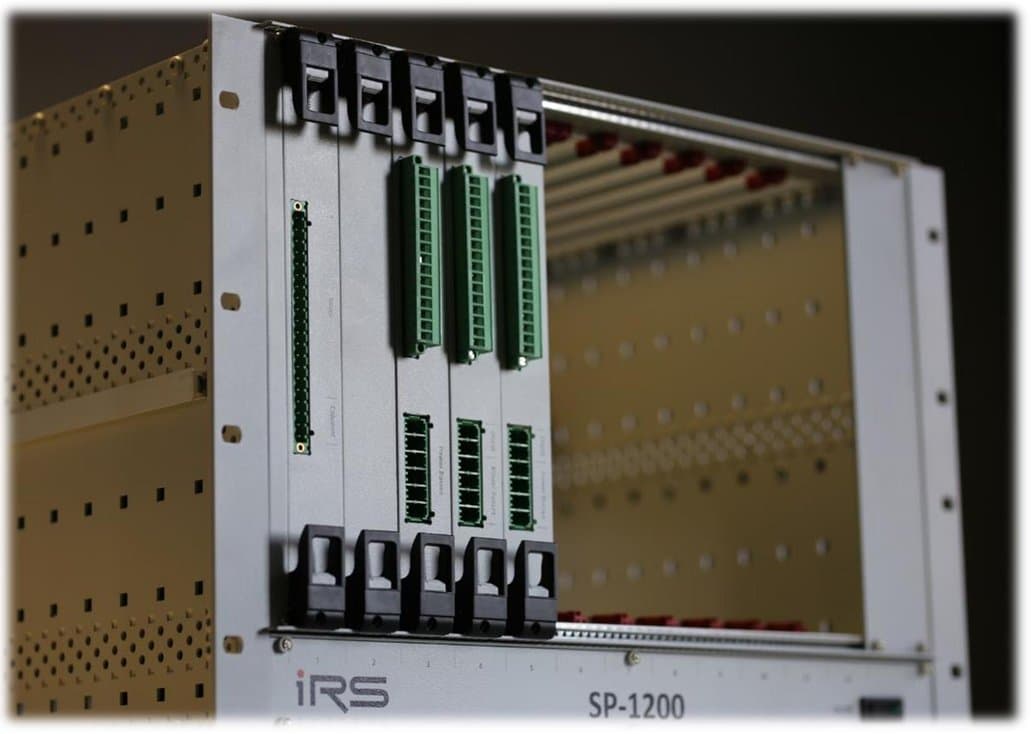
1.2.2Rack Supply Slot
SP-1200 Power Supply requirements: 24Vdc, max. 16A
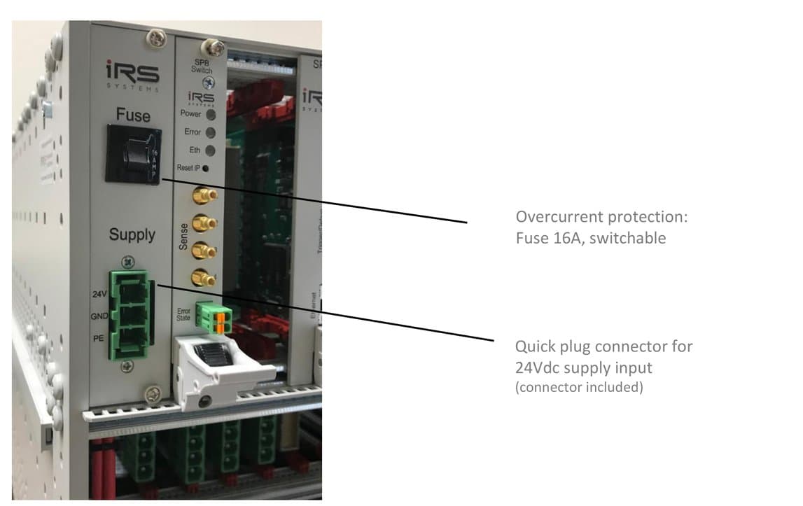
- Overcurrent protection: Fuse 16A, switchable
- Quick plug connector for 24Vdc supply input (connector included)
1.2.3Backplane Interface Card
SP-1200 Backplane signal connectivity to external devices and systems.
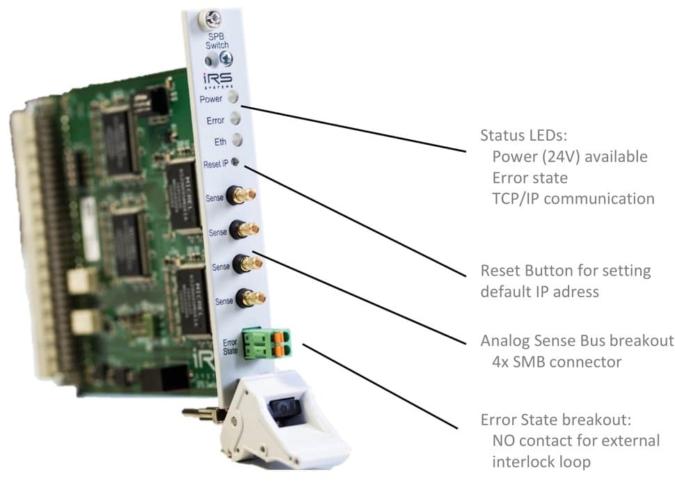
- Status LEDs: Power (24V) available, Error state, TCP/IP communication
- Reset Button for setting default IP address
- Analog Sense Bus breakout: 4x SMB connector
- Error State breakout: NO contact for external interlock loop
1.2.4Switch Module µController Card
- 64x relay driver outputs (switching to GND; 300mA/ch; 10A total)
- 32x analog input channels (4x8 MUX; 12bit; 3,3V)
- 8x Dig. I/O configurable
- 1x CAN, 1x SPI communication
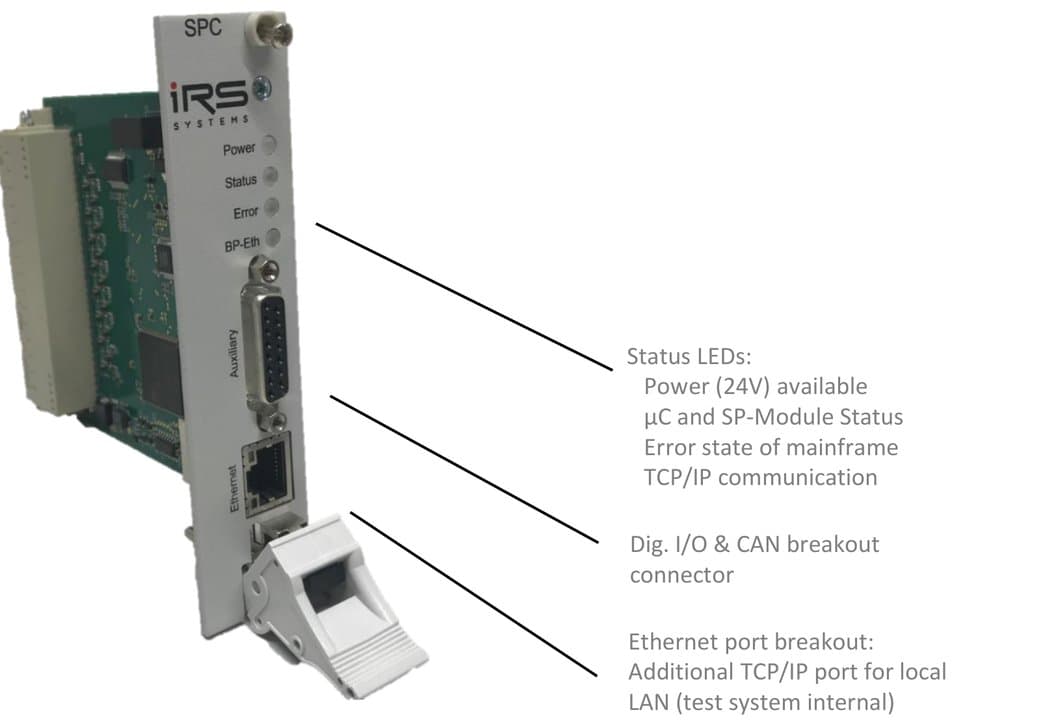
- Status LEDs: Power (24V) available, µC and SP-Module Status, Error state of mainframe, TCP/IP communication
- Dig. I/O & CAN breakout connector
- Ethernet port breakout: Additional TCP/IP port for local LAN (test system internal)
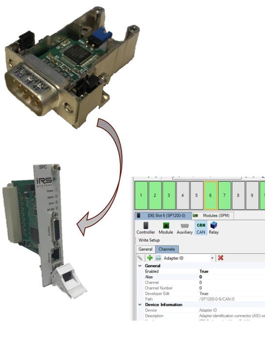
1.2.5Programmable ID Module
- Small CAN communication based ID module
- EEPROM for customer data read/write access
- Fixed worldwide unique ID
- Direct connect to SPC-64 Auxiliary connector read & write via TCP/IP of SPC-64
- Easy configuration via SP Editor SW
Use Cases:
- placed in sub components like DUT Adapters or fixture interface box for automated identification
- system or adapter related data transfer (e.g. calibration data, contacting counters, ..)
1.3SP-1200 Module Portfolio (Q1/22)
1.3.1Loadcard Modules -LC
| Module | I/U Rating | Power Bus | Channels | Diagnostics | Features |
|---|---|---|---|---|---|
| SPM-700401-LC-MF | 70A 60V | -- | 4x1 ch. | current loop | 4 MOSFET switches form A, fuse, I-Sense, theta-Sense |
| SPM-300602-LC | 30A 60V | -- | 6x2 ch. | current loop | Fuse, I-Sense, theta-Sense |
| SPM-100802-LC | 10A 60V | 4 | 8x2 ch. | -- | Fuse, I-Sense, dual-/single channel config, DMM current measurement |
| SPM-100802-LC-MF | 10A 60V | 4 | 8x2 ch. | -- | MOSFET switches, fuse, I-Sense, dual-/single channel config, DMM current measurement |
| SPM-061601-LC | 6A 150V | -- | 16x1 ch. | current loop | 16 form A contacts with load breakout pcb, DMM current measurement |
| SPM-061601-LC-E02 (new) | 6A 60V | 4 | 12x2 ch. | current loop | Dual load extension for 12 channels switchable to 4x power busses, integrated shunt: current measurement ranges 1A, 2.5A, 6A configurable |
| SPM-026401-LC | 2A 60V | 4 | 64x1 ch. | Readback | 64 form A contacts with load config pcb |
| SPM-022404-LC | 2A 60V | 4 | 24x4 ch. | readback | 24x4 topology (1 channel to 4 loads), 4x piggyback pcb‘s for loads, current transducers optional |
1.3.2Matrix Modules -MX
| Module | I/U Rating | Columns | Rows | Diagnostics | Features |
|---|---|---|---|---|---|
| SPM-023206-MX | 2A 60V | 6 | 32 | readback | Topology 32 rows (2A) to 6 columns (10A), each row fused, breakout connector |
| SPM-021604-MX | 2A 60V | 4 | 16 | readback | Topology 16 rows (2A) to 4 columns (10A), each row fused, breakout connector |
1.3.3Fault Simulation Modules -FS
| Module | I/U Rating | Topology | Diagnostics | Features |
|---|---|---|---|---|
| SPM-300802-FS (new) | 30A 60V | 8 Ch. / 2x Fault Bus | current loop | Connects 8x DUT pins (30A each) to 2x 40A fault busses (typ. Vcc and GND), LED indicators |
| SPM-020802-FS-D-FI (new) | 2A 60V | 8x2 Ch. / 2x Fault Bus | current loop | Connects 8 differential DUT pins (2A each) to 2x 40A fault busses (typ. Vcc and GND). Additional 2x MOSFET fast interrupter switches 2A and 40A for Power ON/OFF scenarios |
| SPM-022002-FS (new) | 2A 60V | 20 Ch. / 2x Fault Bus | current loop | Connects 20x DUT pins (2A each) to 2x 40A fault busses (typ. Vcc and GND) |
1.3.4Other Modules
| Module | I/U Rating | Topology | Diagnostics | Features |
|---|---|---|---|---|
| SPM-014002-HV | 1A 1000V | 40 Ch. | -- | High voltage card with configurable topology: 4x10 ch., dual 2x10 ch. or 2x 20 ch. |
| SPM-SYS-001 | -- | 8x2 Ch. | -- | Aux power supply monitoring (5V, 12V, 24V), 16x Dig. IN, 12x Dig. Out, 8x diff. Signal switching |
| SPM-1000201-ME-CMM | 100A 32V | 2x1 Ch. | current loop | 2x calibrated autoranging current measurement channels from µA-100A |
1.3.5Stand Alone Modules -STA
| Module | I/U Rating | Topology | Diagnostics | Features |
|---|---|---|---|---|
| SPM-DRV-001-STA (new) | 16A 48V | 32x Output 2.5A, 50V; 32x Output 0.3A, 30V; 32x LVTTL Input 30V | readback coupling (SW), LED display | 64x open drain outputs (2.5A/0.3A) for high power switching; 16A max. total current; 32x Dig. Inputs, via SW configuration as status readback for switching state validation. Additional features: 8x NO relays 2A, 60V; 2x Temperature sensor inputs; cooling fan and error state contact |
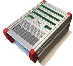
Switching Platform Stand Alone Modules:
- stand alone solutions for distributed switching tasks (no SP mainframe required)
- typical formfactor: small aluminium housing with LxWxH ~190x125x60mm
- connectivity: TCP/IP port of system controller, supply voltage (e.g. 24Vdc), all other specific hardware (e.g. high power relays, control LEDs, ..)
- full integration in SP software (configuration, setting, alias names, debugging windows, ..)
- easy integration as Add On in each existing SP topology (e.g. connect to unused SPC-64 TCP/IP socket)
- note: SPM-…-STA products have different formfactor and are not designed for use inside SP-Mainframes
1.4SP Modules
1.4.1SPM-700401-LC-MF (MOS-FET)
- 4x channels: 70A continuous ON; 85A max. 40 sec ON / 80 sec OFF; 100A max. 20 sec ON / 50 sec OFF
- Current measurement app. 1% (±85A)
- Current and temperature monitoring
- PCB Temp. vs. Current (3 fans on):
| Current | PCB Temp. / time |
|---|---|
| 70A | 95°C / 30 min. |
| 85A | 60°C / 30 sec.; 80°C / 40 sec; 95°C / 60 sec |
| 100A | 60°C / 10 sec; 80°C / 20 sec |
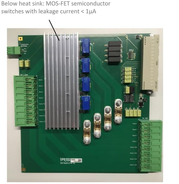
Below heat sink: MOS-FET semiconductor switches with leakage current < 1µA.
Current transducers app. 1% precision, offset referenced. Sensitivity: 25mV/A; Vout: -2,125V .. 2,125V (= -85A..85A).
Power supply switching example
SPM-700401-LC-MF used for switching power supply outputs (up to 70A) to DUT (example configuration).
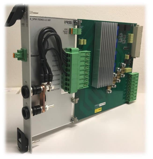
Using two MOSFET channels parallel would allow switching of app. 150A.
Schematic
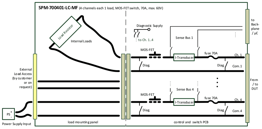
- 4 Channels, each 70 A, 60V
- Integrated current transducers (app. 1%), output voltage connectable to Sense-Bus 1..4; current value also via communication (reduced precision)
- Onboard diagnostic (self test: relay state open/close, current transducers function)
- Overcurrent and overtemperature monitoring -> channel switch to open
- Internal load placement and external load breakout
Load scenarios
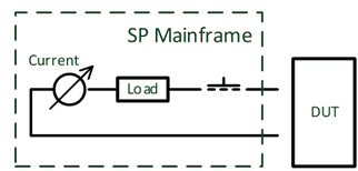
Switch high current load between DUT pins with integrated current measurement (app. 1%):
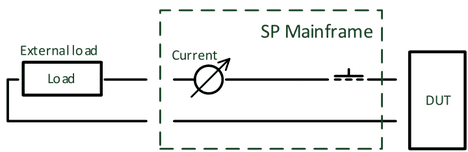
Switch external placed high current load between DUT pins with integrated current measurement (app. 1%):
Connect high current power supply directly to DUT with integrated current measurement (app. 1%):
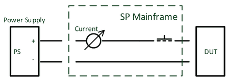
Hot switching possible due to MOSFET switches.
1.4.2SPM-300602-LC
- 6x2 channels 30A (40A max. 60 sec)
- Current measurement app. 1% (±40A)
- Current and temperature monitoring
- Internal diagnostic
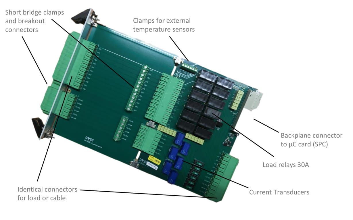
Labeled components: Short bridge clamps and breakout connectors; Clamps for external temperature sensors; Identical connectors for load or cable; Load relays 30A; Current Transducers; Backplane connector to µC card (SPC).
SPM-300602-LC-E: Schematic
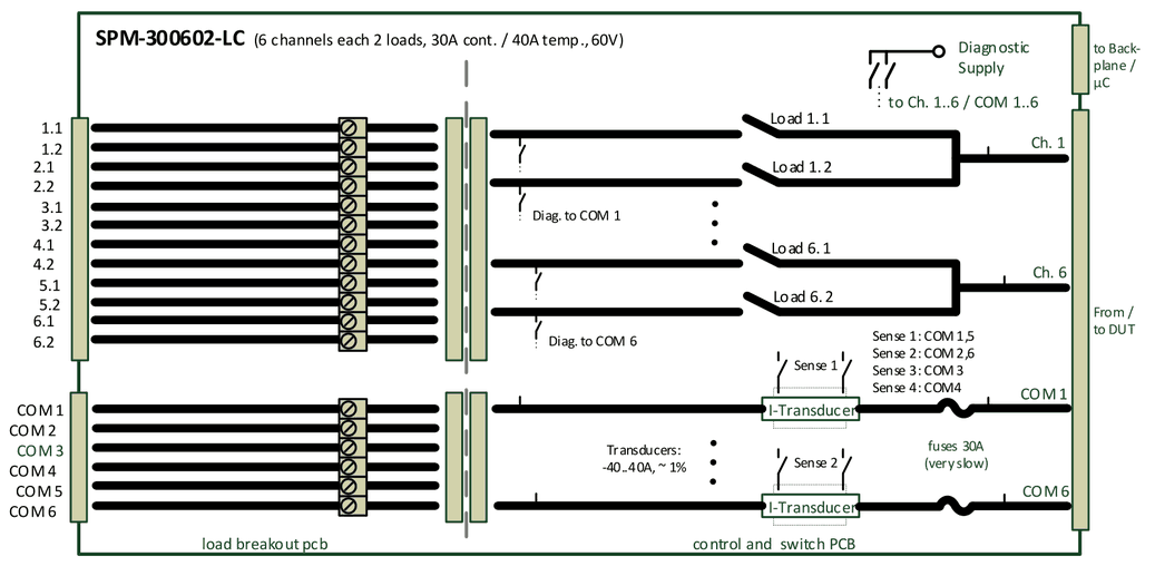
- 6x2 Channels, each 30 A (40 A temporary app. 1 minute), 60V
- Integrated current transducers (app. 1%), output voltage connectable to Sense-Bus 1..4; current value also via communication (reduced precision)
- Onboard diagnostic (self test: relay state open/close, fuse, current transducers function)
- Overcurrent and overtemperature monitoring -> channel switch to open
- Internal load placement and external load breakout
Transducers: -40..40A, ~ 1%. Sense 1: COM 1,5; Sense 2: COM 2,6; Sense 3: COM 3; Sense 4: COM4.
SPM-300602-LC-P: Schematic
SPM-300602-LC with option –P = load mounting panel.
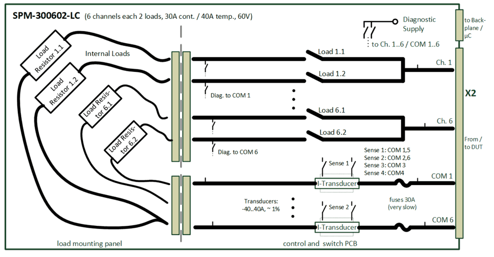
Load scenarios
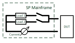
Switch 2 different high current loads between DUT pins with integrated current measurement (app. 1%):
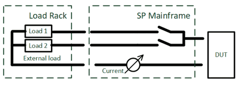
Switch 2 different external placed high current loads between DUT pins with integrated current measurement (app. 1%):
Connect high current power supply directly to DUT with integrated current measurement (app. 1%):
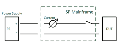
Hot switching not possible.
1.4.3SPM-100802-LC
- 8x2 channels 10A, 60V, fused
- Each channel configuration as dual load or single channel
- Current measurement via shunt, current transducer or in-line DMM
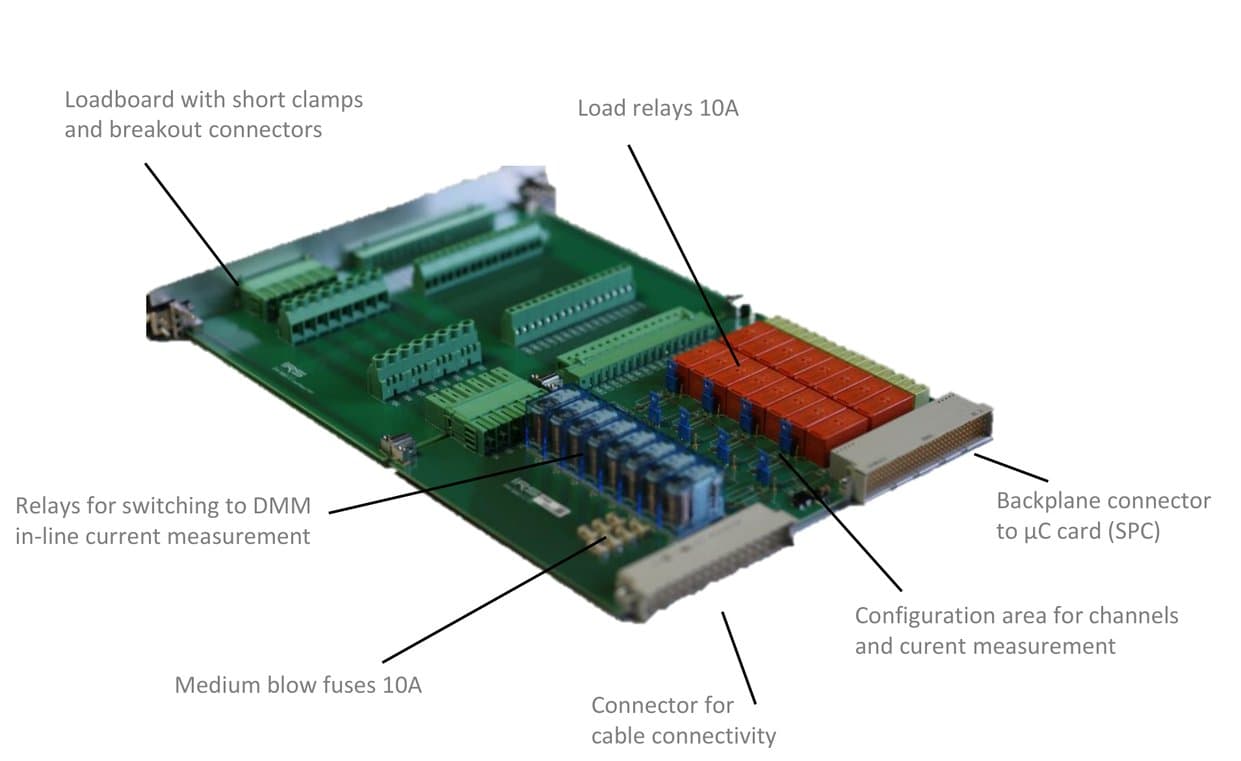
Labeled components: Loadboard with short clamps and breakout connectors; Load relays 10A; Relays for switching to DMM in-line current measurement; Medium blow fuses 10A; Connector for cable connectivity; Configuration area for channels and current measurement; Backplane connector to µC card (SPC).
Current measurement
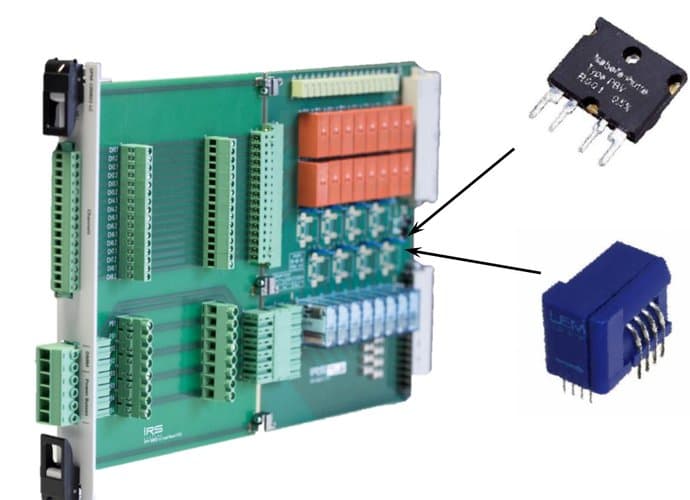
Standard shunts: 25mOhm, 50mOhm, 1Ohm, 10Ohm (0.5..0.05%); 3W max. continuous power; other values on request.
Current Transducer: -12A .. 12A, ~1% precision, 200kHz; Vout offset referenced; Sensitivity: 104,2mV/A; Vout: -1,250V .. 1,250V (= -12A..12A).
Each of the 8 load channels can be configured with shunt or current transducer. Standard delivery state is blank (no shunts or current transducers). On request also mounted or separate shunts or CT-Modules possible.
Schematic
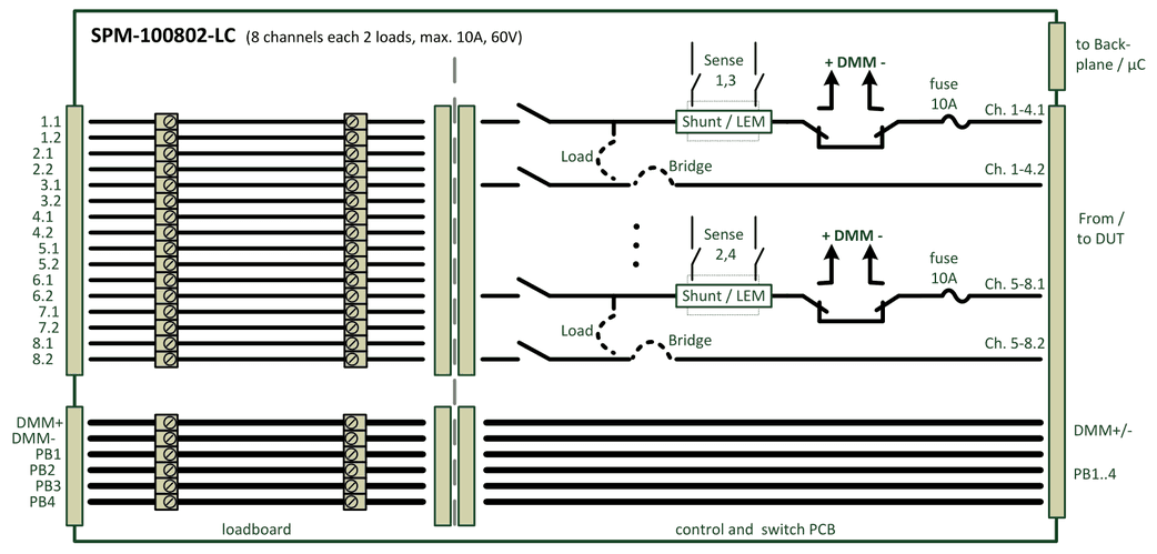
- 8x2 Channels, each 10 A, 60V, 4x Power Bus max. 18A
- Shunt or current transducers, output voltage connectable to Sense-Bus 1..4; 4 parallel current measurements: ch.1..4 to Sense 1 & 3 and ch. 5..8 to Sense 2 & 4
- Direct DMM in-line current measurement on each channel
- Loadboard with breakout connectors and clamps for shorts and smaller loads
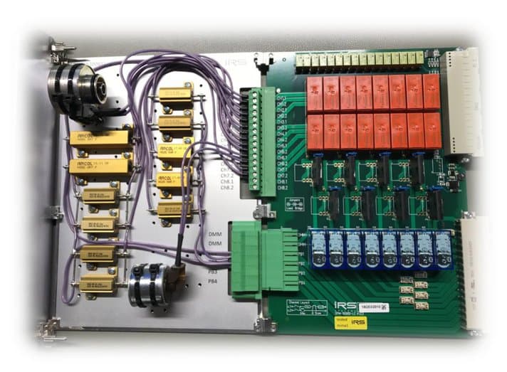
Load configuration example
SPM-100802-LC used for specific load configuration including original motor inductors (example configuration).
1.4.4SPM-026401-LC
- 64x channels form A, 2A, 60V
- 4x power bus lines 10A
- Relay state readback via 2nd contact
- Loadboard for easy load configuration and breakout connector
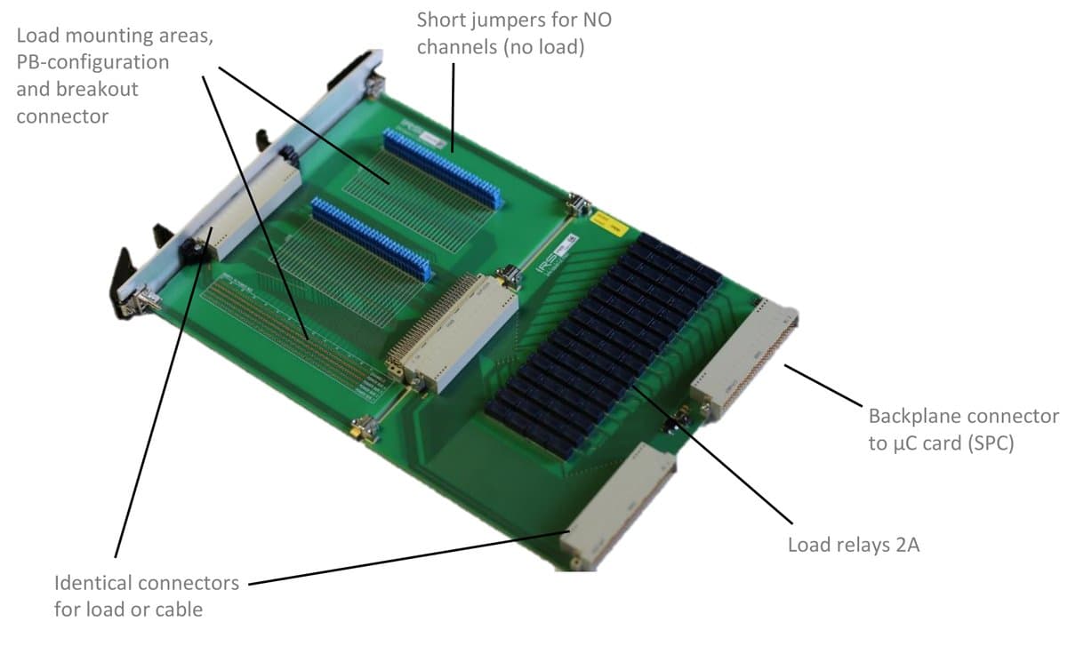
Labeled components: Load mounting areas, PB-configuration and breakout connector; Short jumpers for NO channels (no load); Identical connectors for load or cable; Load relays 2A; Backplane connector to µC card (SPC).
Schematic
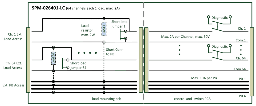
- 64 Channels each 2 A, 60V & 4x Power Bus Lines, 10A each
- Relay switching state monitoring via 2nd contact
- Loadboard for internal loads mounting and external load access
- including 64 short jumpers and external cable side connector
Load scenarios
Use all 64 channels as Form A (SPST) relay contacts with max. current 2A (standard delivery state of all 64 jumpers on loadboard):
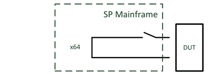
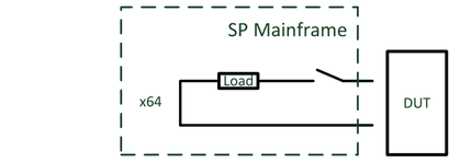
Switch internal placed loads between DUT pins:
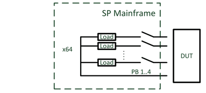
Switch internal placed loads to 4x Power Bus lines (max. 10A per PB line):
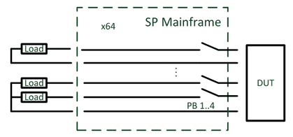
Switch external placed loads between DUT pins or to 4x Power Bus lines (max. 10A per PB line):
1.4.5SPM-021604-MX
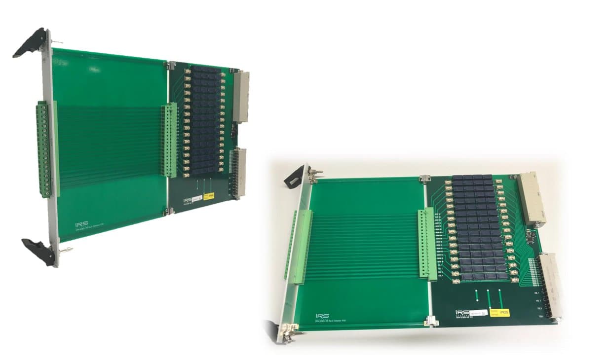
- 16x4 matrix crosspoints, 2A, 60V
- 4x column lines for max. 10A
- 16x row lines 2A, fused
- Relay state readback via 2nd contact
- breakout connectors rows/ & columns
Schematic
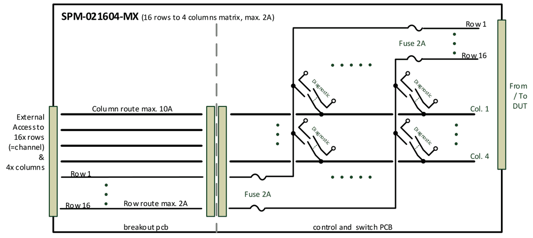
- Matrix 16x4 topology (16 rows/channels to 4 columns)
- Each row/channel max. 2A, 60V, incl. fuse
- Each column max. 10A
- Relay switching state monitoring via 2nd contact
- Loadboard for external access to channels and rows
- including external cable side connector
1.4.6SPM-023206-MX
- 32x6 matrix crosspoints, 2A, 60V
- 6x column lines for max. 10A
- 32x row lines 2A, fused
- Relay state readback via 2nd contact
- breakout connectors rows/ & columns
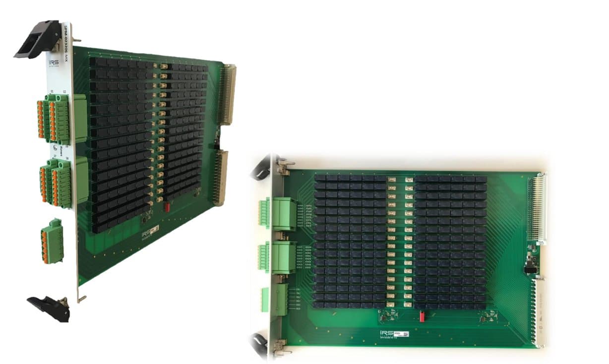
Schematic
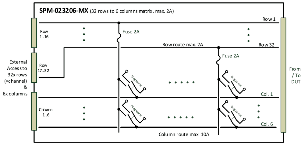
- Matrix 32x6 topology (32 rows/channels to 6 columns)
- Each row/channel max. 2A, 60V, incl. fuse
- Each column max. 10A
- Relay switching state monitoring via 2nd contact
- Breakout connectors for external access to channels and rows
- including external cable side connector
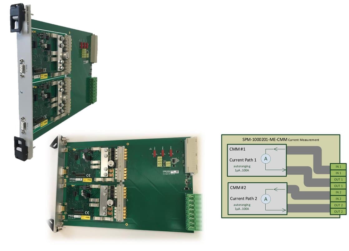
1.4.7SPM-1000201-ME-CMM
- 2x CMM-III or CMM-IV on a SP-Module carrier
- autoranging current measurement from 1µA- 100A on 2 channels
- expandable to max. 8 CMM‘s
- internal diagnostic via loop current
- standard factory or DAkkS calibration
- Full SP-SW support: read current values via TCP/IP commands
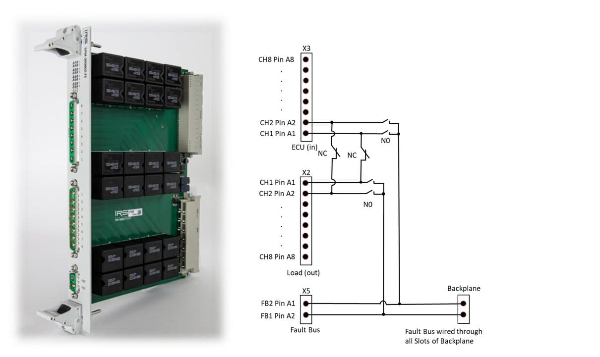
1.4.8SPM-300802-FS
- 8x fault simulation channels 30A, 60V
- 2x fault bus 40A (60A temp.)
- LED indicators, internal diagnostic
- high power breakout connectors
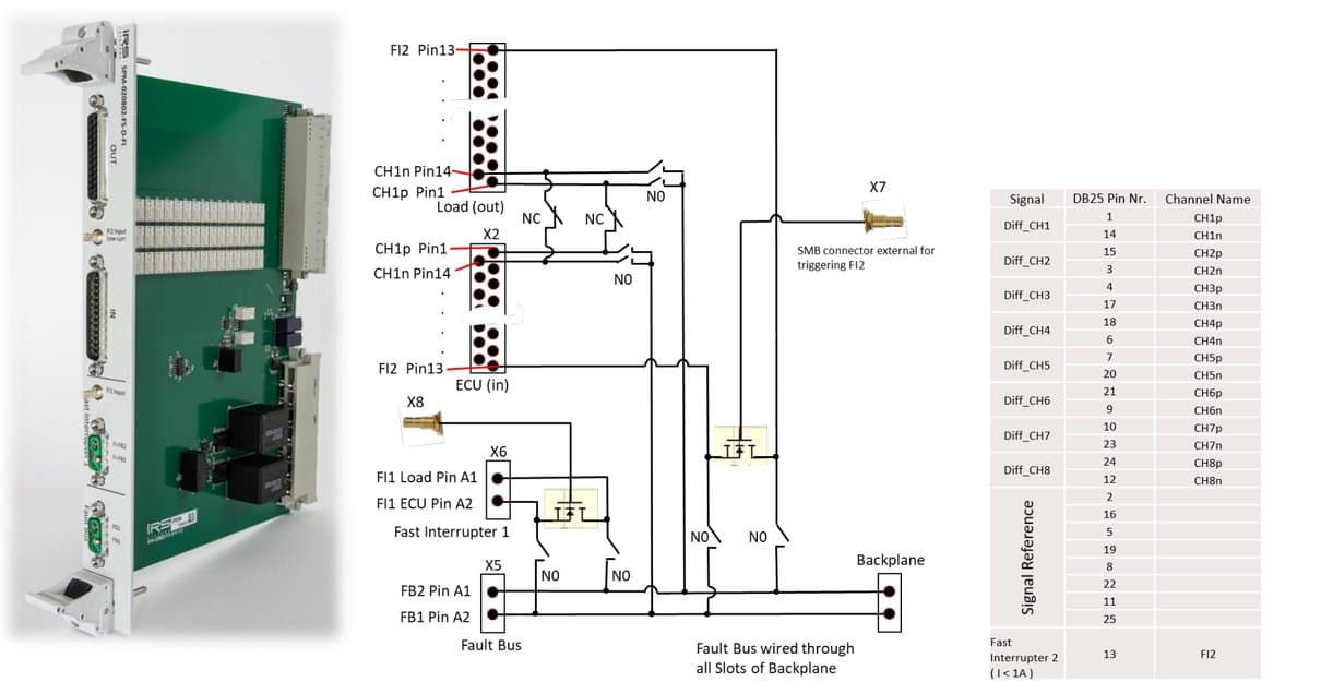
1.4.9SPM-020802-FS-D-FI
- 8x differential channels 2A, 60V
- 2x fault bus 40A (60A temp.)
- 2x fast interrupter (MOSFET, 2A, 40A)
- Internal diagnostic
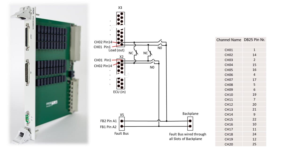
1.4.10SPM-022002-FS
- 20x fault simulation channels 2A, 60V
- 2x fault bus 40A (60A temp.)
- Internal diagnostic
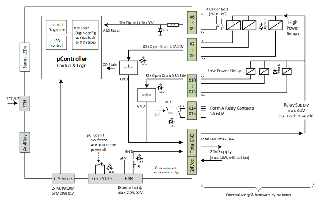
1.4.11SPM-DRV-001-STA
- 32x Open drain outputs 2.5A, 50V
- 32x Open drain outputs 0.3A, 30V
- 32x Dig. Inputs LVTTL max. 30V
- 8x relays form A (normally open) 2A
- 2x temperature sensor inputs
- 16A total current rating
- external fan output
- Error State contact (normally closed)
- Internal diagnostic & LED indicators
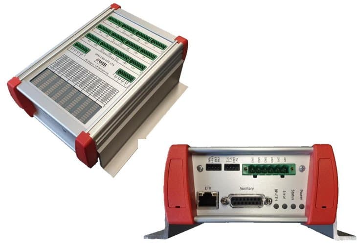
Switching of high power relays and contactors for high power requirements: 32x 2.5A/50V & 32x 0.3A/30V & total current 16A.
Automated readback of contactors AUX contacts to ensure correct switching states: Dig. IN and Dig. OUT can be linked via SW configuration, error raised if AUX state does not match.
Compact stand alone module, TCP/IP communication, distributed topologies.
Block diagram
1.5SP-1200 System Integration
System Integration 19‘‘-Cabinet, 38HU:
- 2x PXI Chassis each 18 slot
- 2x SP-1200 Mainframe each 12 slot
- 4x PS Channels (1x 1.500W, 4x 100W)
- Rack for additional HW (3HU)
- optional UPS or additional PS
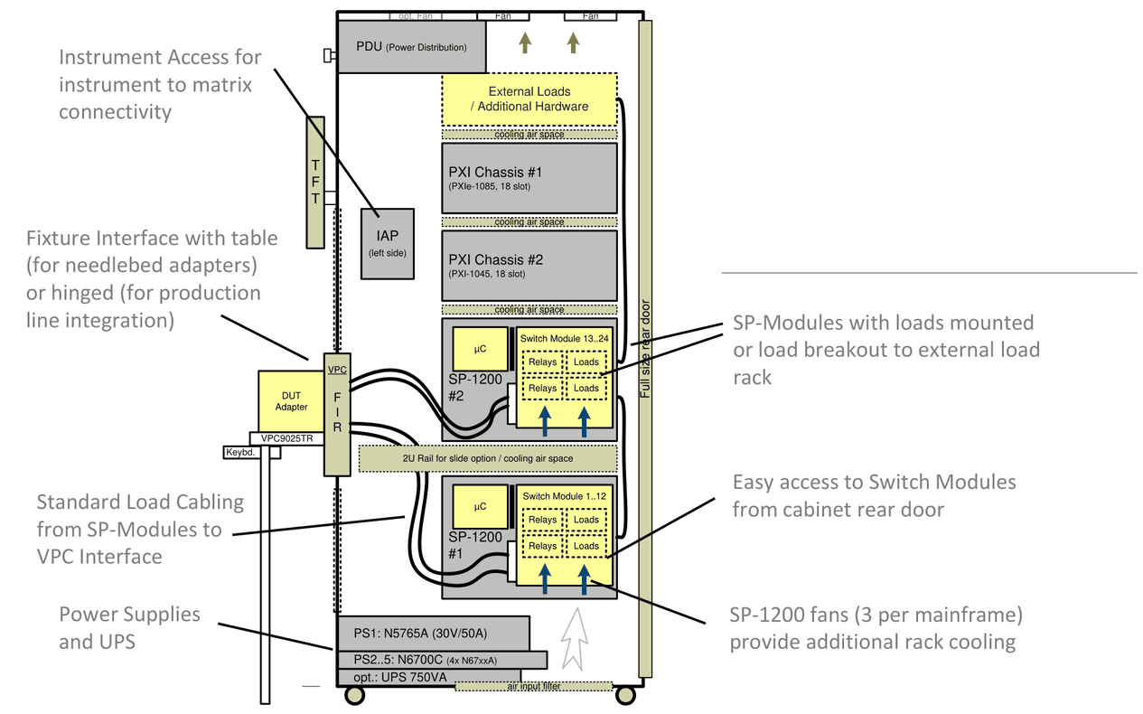
- Instrument Access for instrument to matrix connectivity
- Fixture Interface with table (for needlebed adapters) or hinged (for production line integration)
- Standard Load Cabling from SP-Modules to VPC Interface
- Power Supplies and UPS
- SP-Modules with loads mounted or load breakout to external load rack
- Easy access to Switch Modules from cabinet rear door
- SP-1200 fans (3 per mainframe) provide additional rack cooling
1.6TCP/IP Topology
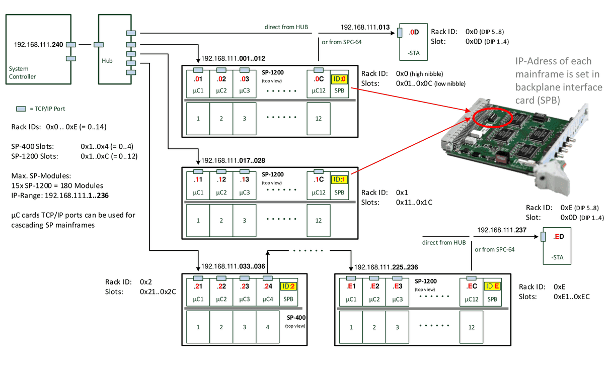
- Rack IDs: 0x0 .. 0xE (= 0..14)
- SP-400 Slots: 0x1..0x4 (= 0..4)
- SP-1200 Slots: 0x1..0xC (= 0..12)
- Max. SP-Modules: 15x SP-1200 = 180 Modules
- IP-Range:
192.168.111.1..236 - µC cards TCP/IP ports can be used for cascading SP mainframes
- IP address of each mainframe is set in backplane interface card (SPB)
Further labels in the diagram:
- System Controller:
192.168.111.240 - -STA
192.168.111.013: direct from HUB or from SPC-64; Rack ID: 0x0 (DIP 5..8), Slot: 0x0D (DIP 1..4) - -STA
192.168.111.237: direct from HUB or from SPC-64; Rack ID: 0xE (DIP 5..8), Slot: 0x0D (DIP 1..4)
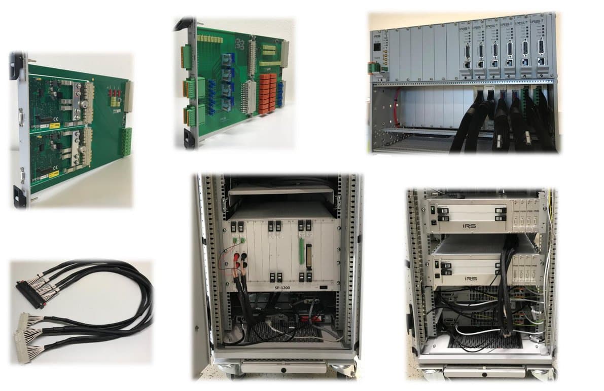
1.7SP-1200 Gallery
Documents and downloads
Further documents and files for your IRS product are available on myIRS.