SP-1200 Mainframe – IRS product 121466 SP-1200, Switching Platform Mainframe 12 slot, v2; hardware version 2.0.
2.1General Description
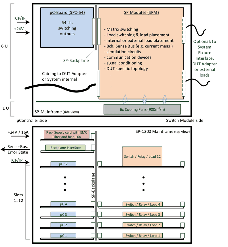
The IRS Switching Platform provides standardized, modular and scalable integration of switching tasks in automated test systems. Typical tasks are load switching, power matrix switching, communication distribution, load path current measurement and signal conditioning. IRS provides a portfolio of modules for that switching functionality, further modules can be developed and built by IRS GmbH on request.
The SP-1200 Mainframe is a 7HU 19‘‘-Rack that controls the switching states of up to 12 Plug-In modules with size 6HU and 6HP standard width.
The Switching Platform Modules (SPM) provide different current classes (2A, 10A, 30A, 70A), space for load mounting, connectivity to external hardware and additional measurement features. The mainframe provides 6 fans in the bottom of the rack for load cooling purposes and internal self-diagnostic features on most modules.
An internal 8 channel sense bus provides measurement signals over all module slots with connectivity to external measurement devices. The high current modules (>30A) provide Internal current and temperature monitoring and activate an Error State output in case of exceeding limitations. All current and temperature values on this high power modules can be read out via communication command.
The SP-1200 mainframe is controlled via TCP/IP connection and up to 15 mainframes can be linked together on one TCP/IP port to increase the total capacity of switching channels.
2.2Safety Instructions
- Only for use in the specified DC Input Range of 24Vdc and in electrical networks providing protection earth (PE).
- Use only inside suitable 19‘‘-Cabinets and not for applications to humans or animals.
- Use modules (SPM) only within specified current and voltage ratings acc. modules Datasheet.
- Outputs need sufficient isolation and protection against contact.
2.3Schematic Overview & Pictures


2.4Delivery Content of SP-1200
The SP-1200 basic mainframe includes following components:
- 19‘‘-Rack 7HU, 475mm depth, color RAL7035, ON/OFF switch, 6x cooling fans
- 12-slot backplane for µC and Switch Module population
- Backplane Interface card incl. Error State cable side connector
- SPB Supply card incl. cable side supply input connector
- Switching Platform Software for setup and configuration
- Filler panels 6HU and 3HU for unused slots (front and rear side closed)
2.5Certification & Compliance
| Item | Value |
|---|---|
| Certification of conformity | CE mark by IRS |
| RoHS Compliance | EU RoHS directive 2011/65/EU; Directive (EU) 2015/863 Annex II |
2.6Used Abbreviations
| Abbreviation | Meaning | Description |
|---|---|---|
| SP | Switching Platform | as general term for all Switching Platform products |
| SPC | Switching Platform Controller | 3HU µC card that controls a Switching Platform Module |
| SPM | Switching Platform Module | 6HU pcb with relays and other circuits controlled by a SPC |
| SPW | Switching Platform Wiring | standardized cable to connect a SPM to system interface |
| HU | Height Unit = 44,45 mm | |
| HP | Horizontal Pitch = 5,04 mm | |
| DUT | Device Under Test | same as UUT (unit under test) |
2.7Electrical
| Item | Value | Remarks |
|---|---|---|
| Supply Voltage | 24 Vdc | |
| Supply Current | max. 16 A | Fused via rack supply card |
| Power Consumption | typ. 50..200 W | depending on modules and switching states |
| Power Consumption | max. 400 W | internal power for all µC, modules and fans |
| PE Connection | Required | to test systems cabinet |
2.8Mechanical
| Item | Value | Remarks |
|---|---|---|
| Width | 19‘‘ | app. 483 mm |
| Height | 7 HU | app. 312 mm |
| Depth | 475 mm | rack depth |
| Weight | app. 10,3 kg | no cabling, slot cover panels |
2.9Environment
| Item | Value | Remarks |
|---|---|---|
| Operating Temperature Range | 0..55 °C; 32..131 °F | |
| Operating Humidity Range | 10-80 % | non condensing |
2.10Mainframe Cooling
6 fans in the bottom of the mainframe (1HU) provide an internal air stream of app. 900m³ per hour. They will be activated (switched ON):
- By Backplane Interface card if the mainframe temperature sensor (located in top middle of mainframe) exceeds 40°C
- By any µController (SPC) that detects a temperature of >40°C on its ADC (on modules or external).
They will be de-activated (switched OFF):
- If no µControllers (SPC) and Backplane Interfaces temperature sensor is measuring >35°C
There are 5°C temperature difference to avoid a fast switching ON/OFF situation for the fans. If e.g. 5 µControllers are requesting the “Fan ON State”, then they will be switched to OFF if none of them is requesting “Fans ON” any more.
In case cooling is not sufficient and temperature still raises, any temperature sensor exceeding the value of +80°C leads to complete mainframes error state set to “1”.
2.11Supply & Integration
The SP-1200 mainframe provides a green quick lock 3 pin supply connector for 24Vdc, GND and PE of test systems cabinet on the rack supply slot panel.
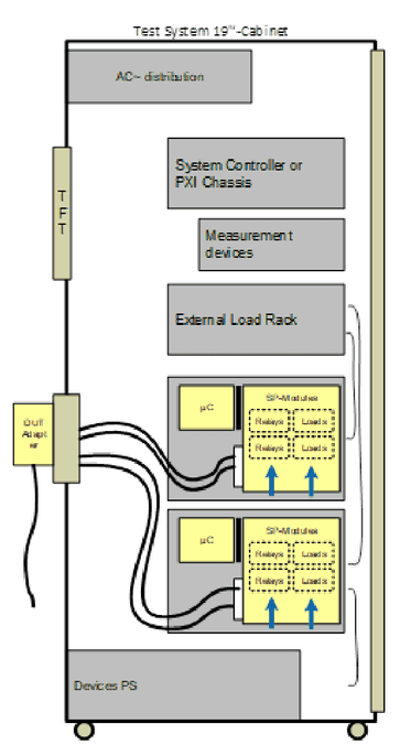
Mechanical integration in 19’’-Cabinet via standard L-profile rails. Alternative C-profile rail integration is possible.
The schematic shows an example of basic mechanical and electrical integration of two SP-1200 mainframes in one 19’’-Cabinet of a typical functional test system.
2.12Basic Topology & Design
List of basic IRS Switching Platform design and topology issues:
- Modular concept: switch module side (6HU) for switching execution and load placement. µC side (3HU) of mainframe for communication and switching control.
- The SP Modules basically focus on switching execution and do not contain any control components. Switching control is provided exclusively by separate µController card.
- Each slot with a populated 6HU Switch Module (SPM) requires a 3HU µController card (SPC) connected to the µController side of the slot.
- All modules support 8 channel sense bus access. This allows e.g. 4 current measurements parallel on different load channels.
- Communication to test system controller via TCP/IP protocol, cable connected to one of the µControllers (SPC) in the mainframe.
- Firmware 100% supports multithreading down to module level. Means each module can be controlled by different thread.
- Most modules provide internal diagnostic circuits and features.
2.13Features & Functions
| Feature | Description |
|---|---|
| Module Capacity | Up to 12 SP-Modules (SPM) with standard width 6HP (app. 30mm) can be populated in one mainframe |
| Communication | Via TCP/IP connection, e.g. 192.168.111.240; cable connected to one of the µControllers (no matter which one); cascading of max. 15 mainframes on one TCP/IP port |
| Current Range | Switch Modules classification (max. current): 2A, 10A, 30A, 70A |
| Voltage Range | typ. 48-60Vdc (see module specification); HV Switching matrix module up to 1.000Vdc (1kV) |
| Load Cooling | 6 cooling fans on bottom of rack, air stream app. 900m³ per hour; activation via API command and on module request (temp.-sensors) |
| Digital I/O (per SPC) | 2 bit digital IN, 2 bit dig. OUT per µController card; max. 2mA TTL 3.3V read/set via SW command |
| Error State Contact | Form A relay contact on backplane interface card for internal error state. Contact is closed when no internal error is detected and opens in case of error. Error reasons are: SW freeze (firmware inside SP-1200); Over-Current detected on any high current load channel; Over-Temperature in mainframe or on any high current load channel |
| Current Monitoring | High current modules (>30A) provide internal current monitoring incl. channel switching OFF function: Load channel will be switched OFF by firmware, if current exceeds limit |
| Temperature Monitoring | High current modules (>30A) provide internal temperature monitoring incl. channel switching OFF function: Load channel will be switched OFF by firmware, if current exceeds limit |
| Analog Sense Bus | SP backplane provides 4 ch. dual wire analog sense bus; via 4x SMB connectors on backplane interface; connecting e.g. a DMM allows measuring the voltage drop of an integrated shunt or output voltage of current transducer on the load channels. Basically 4 currents could be measured in parallel. Note: Not all SP-Modules and load channels support current measurement; Load channels may be switched to dedicated sense busses, see module specification |
SP-Editor SW: The topology and population of IRS Switching Platform products can be configured with a SW tool, the Switching Platform Editor:
- SP project definition and handling
- Mainframes, modules and µC configuration
- Auto-Setup function and configuration report file
- Module dependent parameters (e.g. relay bouncing time)
- Alias names for channels (easy understandable switching)
- Current and temperature limits (high current cards 30A, 70A)
- Access levels Operator, Developer, Administrator password protected
- Firmware and database update
- Debug windows for manual control
- Integrated command request builder and documentation
- …
2.14Backplane Interface
2.14.1Connectivity & Status
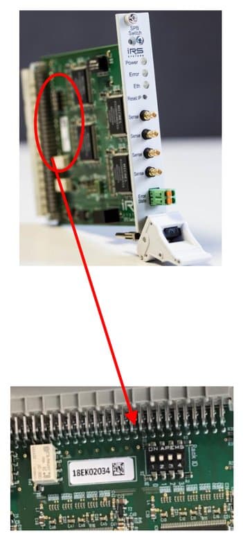
Backplane interface provides access to SP-1200 mainframe’s analog sense bus (8ch.) and the Error State output. The card shows mainframes status conditions via the LEDs Power, Error and Ethernet and allows an IP reset.
The interface also works as a switch for internal TCP/IP distribution to each slot (each slot has own IP address).
For each SP-1200 mainframe the IP Address has to be set in this interface card.
2.14.2IP Address Setting
Default value of each SP-1200 mainframes IP Address is: 192.168.111.0
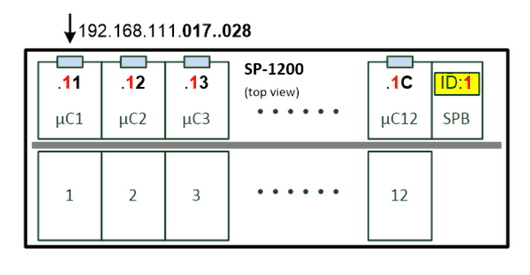
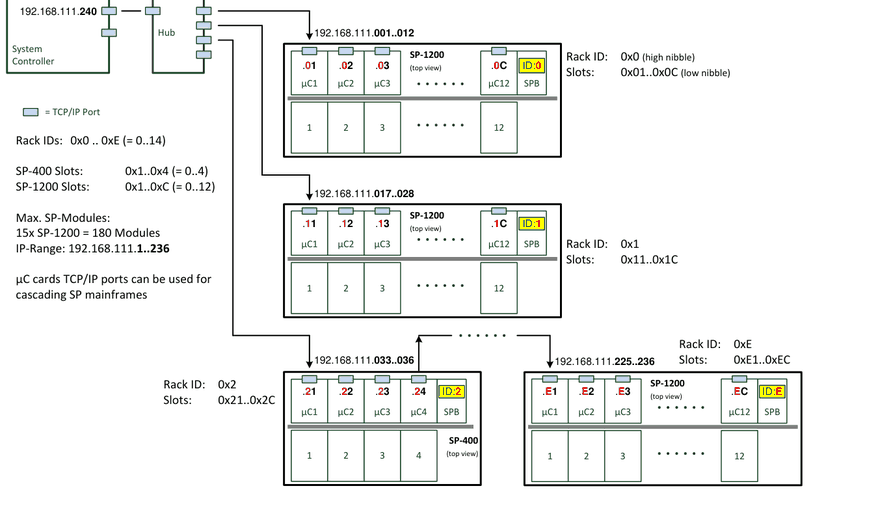
With a 4pin DIP switch on the backplane interface card (right side next to the SNr. Label) the Rack-ID can be set from “0x0” to ”0xE”. This also sets the high nibble of last part of the IP Address. The low nibble is defined by hardware from “0x1” to “0xC” for each slot.
This defines following default IP Address structure in the SP-1200:
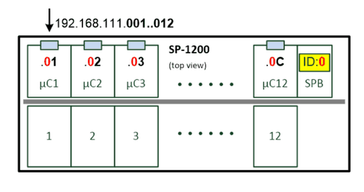
Setting the Rack-ID switch from “0” to “1” changes the mainframes IP Address range:
Example topology with multiple SP Mainframes:
2.14.3Controller IP Setting
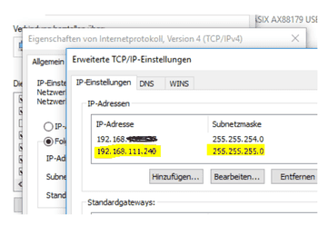
The IP Address range for a Switching Platform topology with 15 SP-1200 mainframes is from 192.168.111.1 up to 192.168.111.236. To avoid collisions, a good IP Address for a controller (PC, Laptop, PXI-Controller, ..) would be e.g.: 192.168.111.240.
2.14.4Change Mainframes IP Address
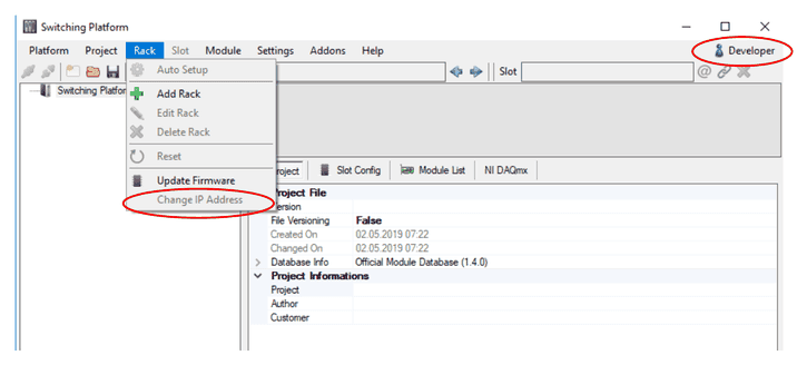
The mainframes IP address can be changed via the SP Software: Rack – Change IP Address. This requires developer login.
2.15Rack Supply Card
The 24Vdc supply voltage for the SP-1200 mainframe is applied via the green 3pin Quick Lock connector. For removal both locking springs need to be pressed to unplug the connector.
+24Vdc, GND and test systems PE need to be connected, the cable side connector is included in delivery. The input is fused with 16A.
All wires need minimum width AWG14 or equivalent 2,5mm².
| Signal | Pin | Position |
|---|---|---|
| +24Vdc | 1 | Top pin |
| GND (24V) | 2 | Middle pin |
| PE | 3 | Bottom pin |

2.16Switching Platform SW
With each SP-1200 mainframe the Switching Platform SW is delivered. Installation of this SW provides .NET API functions, wrapper functions for C, the IRS module database and a SP-Editor.
The Switching Platform Editor is a tool for comfortable configuration of the complete Switching Platform topology in the test system. All mainframes and their IP Addresses including their module population can be defined and stored in a project file with this tool.
The project file needs to be loaded in the test sequence beginning to allow the control of all switching paths and other functions.
Following files are provided: .exe files for installation on 32-bit or 64-bit systems, Firmware for SP µControllers (.ebin file) and the SP Module Database (.spm file) that includes all available SP-Modules and their parameters.
The .NET Framework 4.7 need to be installed on the controller to run the SP SW.
2.17Sense Bus Measurement
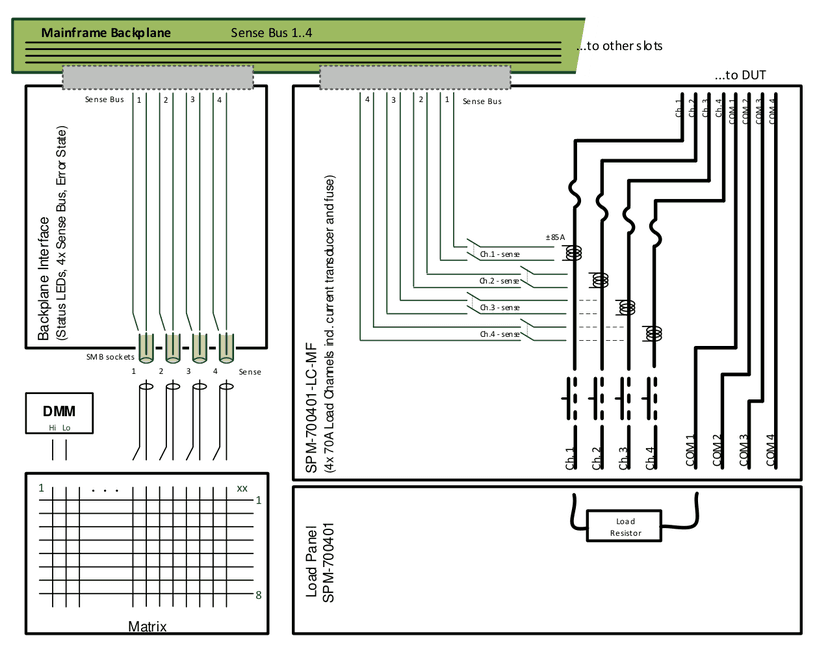
The internal Sense Busses 1..4 can be connected via 4x SMB sockets to external measurement devices (e.g. via some measurement matrix). Shunts or current transducers on the load channels can be connected to the Sense Busses 1..4 by closing the sense relays on the module.
This topology allows in general 4 parallel measurements inside the SP mainframe. Not all load channels can be switched to every sense bus, possible connections are defined in the modules datasheet.
The firmware verifies that only one sense relay is connected to a sense bus at the same time. If already another channel is connected, the API function responds an error.
Example with 70A high current module:
2.18Error State
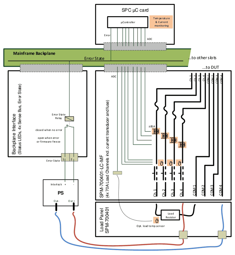
The Error State output reflects mainframe internal errors to devices outside of the mainframe in order to react on critical conditions. Via ADC inputs each µC card (SPC) is monitoring the current and temperature sensors on the module in the corresponding backplane slot. In case of limit exceeding, the SPC sets the Error State to “1” for the whole mainframe.
Main purpose is to connect the Error State output to the Interlock input of a power supply, so in case of an error the PS will switch off and remove potentially dangerous voltage and current from test system and DUT.
The error state can also be connected to e.g. dig. I/O devices read by test systems controller to react inside test sequence on error state condition.
The Error State is set to “1” (means relay contact opens):
- Over current condition: Any load channels current monitoring detected a current exceeding the set limits (set in SP-Editor by default or custom specific).
- Over temperature condition: Any load channels or modules temperature monitoring detected a temperature exceeding the set limits (set in SP-Editor by default or custom specific). Some modules also provide external temperature sensors. This sensors can be used also outside of the SP mainframe e.g. in the test systems cabinet. Independent from SP-Modules the mainframe has a temperature sensor located on top middle of the rack. Via the backplane interface this sensor will activate the fans when >40°C and also raise overtemperature condition when >80°C.
- Firmware freeze: Internal running firmware is re-setting the error state permanently to „0“. If this function is not executed, the error state will switch to „1“ by HW circuits.
In case of Error State is “1”, each API command sent to mainframe will receive a corresponding error message and the command will not be executed.
The Error State can be reset by API function.
Functional schematic with 70A high current module:
2.19Populating & Removal of Modules
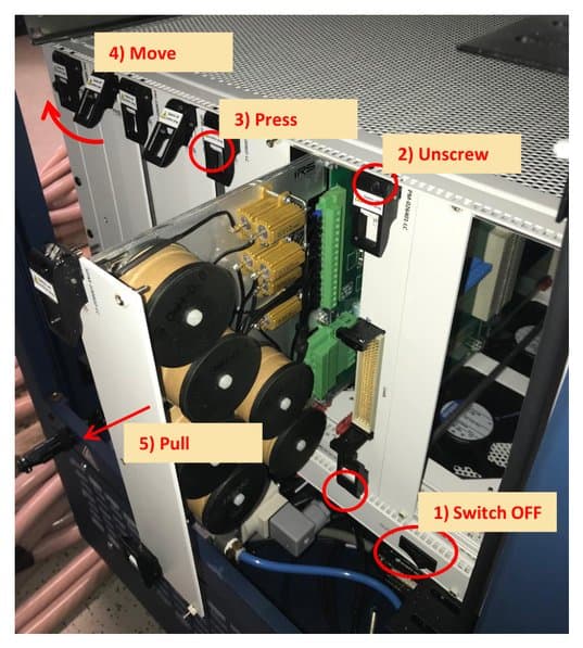
- Disconnect 24V supply or switch off the mainframe before plugging/removing cards.
- To remove modules, first unscrew the panels on top and bottom of SPM holder
- Then press grey locks at the same time and
- Move the holders to unplug the cards from backplane and modules cabling connectors
- Pull the module carefully out of the slot
- Some modules have components mounted on pcb bottom side (left side). To avoid collision with panels of neighbor modules and damage the module the movement must be done very sensitive.
For plugging of modules perform the reverse procedure from 5. to 2. with unpowered or switched OFF mainframe.
2.20List of Available Modules
| Module ID | Module Type | Description |
|---|---|---|
| SPM-300801-FS | Fault Simulation 8 Ch. 30A | Connect DUT pins to short busses |
| SPM-014002-HV | High Voltage Matrix 1kV | 40 ch. 1A configurable High Voltage Matrix |
| SPM-021604-MX | Matrix 16x4 ch. 2A | 16 rows (2A) to 4 columns (10A), selftest: relay readback |
| SPM-023206-MX | Matrix 32x6 ch. 2A | 32 rows (2A) to 2 columns (10A), selftest: relay readback |
| SPM-026401-LC | Loadcard 64 ch. 2A | 64x form A contacts 2A, selftest: relay readback, load breakout pcb |
| SPM-100802-LC | Loadcard 8x2 ch. 10A | 8x2 form A contacts 10A, current measurement by shunt or current transducer, mounting panel or load breakout pcb |
| SPM-300602-LC | Loadcard 6x2 ch. 30A | 6x2 form A contacts 30A, selftest: test current loop, mounting panel or load breakout pcb |
| SPM-700401-LC | Loadcard 4 ch. 70A | 4x form A contacts 70A, selftest: test current loop, mounting panel or load breakout pcb |
| SPM-700401-LC-MF | Loadcard 4 ch. 70A | 4x MOS-FET switches 70A, selftest: test current loop, mounting panel or load breakout pcb |
| SPM-SYS-001 | System Module | System Module; 8x diff. signal switching, auxiliary DC power supply, monitoring (5V, 12V, 24V), 16x Dig. IN, 12x Dig. OUT |
| SPM-1000201-ME-CMM | Measurement Module current µA – 100A | 2x CMM-III autoranging current measurement devices, incl. factory- or DAkkS-calibration, selftest: current loop |
2.21Sparepart List
| Manufacturer / Supplier | Part Nr. | IRS Part Nr. | Component Description |
|---|---|---|---|
| IRS GmbH | SP-1200 | 121466 | Mainframe Switching Platform 12 slot v2 |
| IRS GmbH | SPB Switch | 119151 | SP Backplane Interface card |
| IRS GmbH | SPB Supply | 121461 | SP Supply card v1.1 |
| IRS GmbH | SPC-64 | 120701 | SP µController card v2.2 |
| Würth Elektronik | 691304530003 | 121013 | Supply connector 3pin |
| Phoenix Contact | FMC 1,5/ 2-ST-3,81 | 109439 | Error State Output connector 2pin |
2.22Product Support
- IRS Homepage: www.irs.systems
- Email Contact: info@irs.systems
Documents and downloads
Further documents and files for your IRS product are available on myIRS.