SPM-021604-MX – IRS product 119357 SPM-021604-MX-E, 4x16 Matrix, 2A, breakout pcb; hardware version 1.1.
3.1General Description
The SPM-021604-MX is a low current 6HU switching module for use inside IRS Switching Platform mainframes. The module provides a 4 columns x 16 rows matrix topology for max. 2A per row and 10A current per column.
Each of the 16 rows (= channels) is fused with a 2A fast fuse on DUT input side and additional on the breakout side.
Internal diagnostic is possible via crosspoint switching state readback also available as an API function. More matrix cards can be combined (e.g. via the breakout connector) to increase the number of rows/channels.
Typical tasks are flexible load, measurement and supply switching to DUT pins up to 2A current. The module is available with a metal panel with a closed front panel and a breakout extension pcb for wiring to external devices or other matrix cards.
3.2Safety Instructions
- Only for use in IRS Switching Platform mainframes (e.g. SP-1200) and within the specified electrical limits.
- Use only inside suitable 19‘‘-Cabinets and not for applications to humans or animals.
- Use this SP module only with the SPC-64 µController card (PN: 120701) and with the SP-Editor SW and its API commands for configuration and control
- Hot switching is NOT recommended on any circuit of the module. This will reduce the lifetime and maximum switching cycles of the relays and possibly destroy the relays on the module.
- The module is designed for resistive loads, user has to care about protection circuitry when using inductive or capacitive loads
- Outputs need sufficient isolation and protection against contact.
3.3Schematic Overview & Pictures


3.4Scope of Delivery
SPM-021604-MX-E:
- Switching pcb completely assembled with breakout pcb
- Frontpanel with breakout connectors and all required cable side connectors
3.5Certification & Compliance
| Item | Value |
|---|---|
| Certification of conformity | CE mark by IRS |
| RoHS Compliance | EU RoHS directive 2011/65/EU; Directive (EU) 2015/863 Annex II |
3.6Used Abbreviations
| Abbreviation | Meaning | Description |
|---|---|---|
| SP | Switching Platform | a general term for all Switching Platform products |
| SPB | Backplane Interface | Interface card for SP Mainframe (e.g. SP-1200) |
| SPC | Switching Platform Controller | 3HU µC card that controls a Switching Platform Module |
| SPM | Switching Platform Module | 6HU pcb with relays and other circuits controlled by a SPC-64 µController card |
| SPW | Switching Platform Wiring | standardized cable from a SPM to system interface |
| DUT | Device Under Test | same as UUT (unit under test) |
| CT | Current Transducer | inductive current measurement device |
| HU | Height Unit = 44,45 mm | |
| HP | Horizontal Pitch = 5,04 mm |
3.7Electrical
3.7.1Matrix Channel Specification
| Item | Value | Remarks |
|---|---|---|
| Rated Voltage | 60 Vdc | stationary |
| Rated Current / Channel | 2 A (row); 10 A (col) | stationary |
| Switching Power (resistive load) | 2 A at <30 V; 1 A at <60 V | -> hot switching reduces lifetime ! |
| Fuse / Channel | 2 A | fast fuse, per row (DUT side and breakout side) |
This values include the complete load channel incl. all components (connectors, pcb routes, fuse, current transducer, ..).
3.7.2Relay Specification
The current and voltage ratings of the relay are shown for information only. The “Load Channel Specification“ table shown above has to be used when creating a circuit using this module. The ratings in the “Load Channel Specification“ table are lower than the ratings for the relay by itself.
| Item | Value | Remarks |
|---|---|---|
| Max. Current | 2 A | stationary |
| Max. Voltage | 220 V | DC stationary |
| Switching Power (resistive load) | 2 A at <30 V; 1 A at <60 V; 0,3 A at 220Vdc | hot switching reduces lifetime! |
| Operating Time | max. 4 ms | excl. bouncing time |
| Mechanical Life | > 1x10^8 cycles | without el. load |
3.8Mechanical
| Item | Value | Remarks |
|---|---|---|
| Width | 6 HP | = 30,24 mm; standard width (1 slot) |
| Height | 6 HU | = 266,7 mm |
| Depth | ~ 365 mm | |
| Weight | ~ 0,640 kg |
3.9Environment
| Item | Value | Remarks |
|---|---|---|
| Operating Temperature Range | 0..55 °C; 32..131 °F | |
| Operating Humidity Range | 10-80 % | non condensing |
3.10Topology & Functions
| Item | Value | Description |
|---|---|---|
| Nr. of channels | 16 x 4 | Matrix topology with 64 crosspoints: 16 rows connectable to 4 columns |
| Loads / Channel | 1 | signal per channel |
| Fused Channels | 16 | 16 channels, fast fuse 2A DUT and load side |
| Internal Diagnostic | yes, readback | 2nd relay contact allows readback of switching state via API command and internal diagnostic to verify contact functionality; incl. report generation |
| Load Options | -E | External breakout pcb |
| User ID | Yes | Via SP-Editor a user defined identification string will be stored in modules EEPROM (e.g. Load ID, ..) |
| Memory Objects | Yes | Via SP-Editor memory objects can be defined and stored in modules EEPROM (e.g. calibration data, additional module information, ..); max. 6kB |
| Load Relay Cycle Counter | yes | switching cycle of each relay is counted and stored in modules EEPROM; status can be read via SW command |
3.11Sense Bus Measurement
No current measurement and Sense Bus available on this module.
3.12Component Location
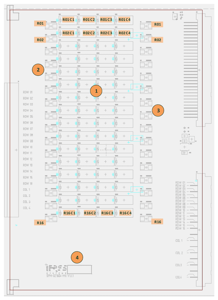
| No. | Component |
|---|---|
| 1 | Crosspoint relays for row 1 - 16 & column 1 – 4 |
| 2 | Fuse breakout side 2A for row 1 - 16 |
| 3 | Fuse DUT side 2A for row 1 - 16 |
| 4 | Serial number and quality check labels |
3.13Connectivity
3.13.1DUT Side Connector Pinout
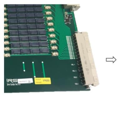
SPM-021604-MX connector X2:
| Pin | z | d |
|---|---|---|
| 2 | Row 1 | Row 2 |
| 4 | Row 3 | Row 4 |
| 6 | Row 5 | Row 6 |
| 8 | Row 7 | Row 8 |
| 10 | Row 9 | Row 10 |
| 12 | Row 11 | Row 12 |
| 14 | Row 13 | Row 14 |
| 16 | Row 15 | Row 16 |
| 18 | ||
| 20 | Col 1 | Col 1 |
| 22 | ||
| 24 | Col 2 | Col 2 |
| 26 | ||
| 28 | Col 3 | Col 3 |
| 30 | ||
| 32 | Col 4 | Col 4 |
X2 connector layout for cable to DUT/Adapter
For cabling to system’s receiver interface or to DUT Adapter following data needs to be considered:
| Item | Value | Remarks |
|---|---|---|
| Max. current | 6 A | per connector pin (crosspoints limited to 2A!) |
| Used pins | 1 | pins used per row |
| Used pins | 2 | pins used per column |
| Wire cross sections | AWG 20 / 0,5 mm² | per row wire |
| Wire cross sections | AWG 16 / 1,5 mm² | per column wire |
3.13.2Breakout Connector Pinout
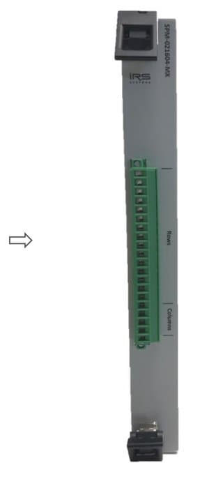
| Breakout pin | Signal |
|---|---|
| 1 | Row 1 |
| 2 | Row 2 |
| 3 | Row 3 |
| 4 | Row 4 |
| 5 | Row 5 |
| 6 | Row 6 |
| 7 | Row 7 |
| 8 | Row 8 |
| 9 | Row 9 |
| 10 | Row 10 |
| 11 | Row 11 |
| 12 | Row 12 |
| 13 | Row 13 |
| 14 | Row 14 |
| 15 | Row 15 |
| 16 | Row 16 |
| 17 | Col 1 |
| 18 | Col 2 |
| 19 | Col 3 |
| 20 | Col 4 |
The breakout connector can easily be used as parallel matrix crosspoints access e.g. for debugging purposes.
For cabling to breakout interface following data needs to be considered:
| Item | Value | Remarks |
|---|---|---|
| Max. current | 12 A | per connector pin (crosspoints limited to 2A!) |
| Used pins | 1 | pin used per row and per column |
| Wire cross sections | AWG 20 / 0,5 mm² | per row wire |
| Wire cross sections | AWG 16 / 1,5 mm² | per column wire |
3.13.3Linked Matrix Columns
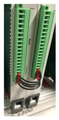
Multiple SPM-021604-MX Matrix modules can be used either with separated columns, or the columns can be linked together to achieve more crosspoints (e.g. 4x 32 or 4x 48, ..).
The connection of the columns between the modules can be done on X2 connector side as an SP-1200 internal wiring. Alternatively this connection can be done on the breakout connector as shown on the picture.
3.14Relay State Readback
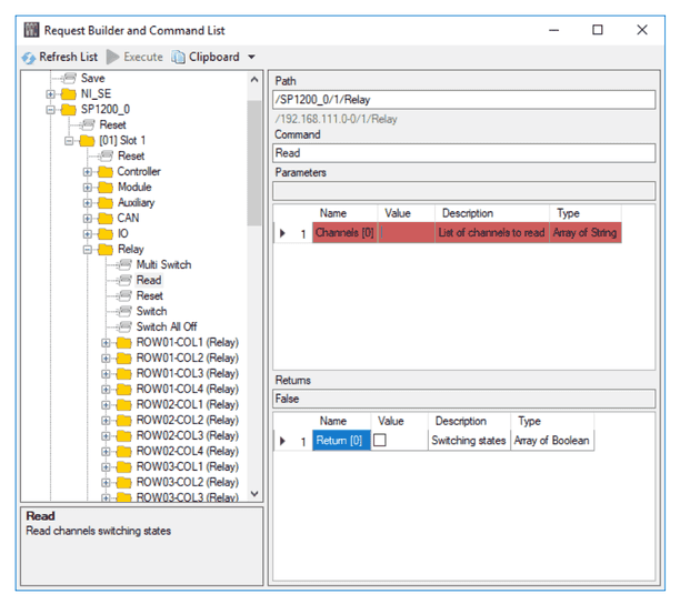
The second contact of cross point relay is card internally used for switching state indication. Via API command the state of cross point relay(s) can be read back.
3.15Diagnostics & Selftest
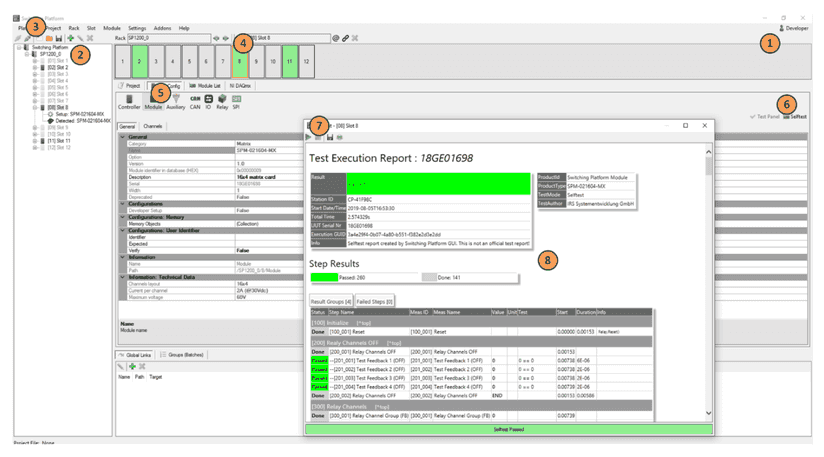
The SPM-021604-MX provides internal selftest sequence that switches each single crosspoint and verifies the switching state. After performing the selftest sequence a report is generated that can be stored by user for documentation purposes.
Start Switching Platform Editor SW – (1) login as developer – (2) load project configuration file or add new mainframe with autodetect – (3) connect SP mainframe – (4) select slot with SPM-021604-MX card – (5) select “Slot Config” Tab and “Module” – (6) select “Selftest” – (7) run selftest by pressing blue arrow – (8) review/save selftest report
3.16Sparepart List
| Manufacturer / Supplier | Part Nr. | IRS Part Nr. | Component Description |
|---|---|---|---|
| Panasonic | TX2-24V | 112828 | Relay 2A, 2 form C, 24Vdc |
| Littelfuse | 0154002.DR | 119358 | Fuse 2A, SMD |
| Phoenix Contact | MSTB 2,5/20-STF-5,08 | 118491 | Breakout connector cable side, 20 pin |
| Harting | DIN41612 VG-48F | 101422 | X2 cable side female connector |
3.17Product Support
- IRS Homepage: www.irs.systems
- Email Contact: info@irs.systems
Documents and downloads
Further documents and files for your IRS product are available on myIRS.