4.1EME Overview
Every single EME covers a 3-phase system. Two identical EME may be optionally combined to simulate a 6-phase motor, where one system acts as master and one as slave.
4.2Power stage
Every IRS EME active motor load contains a 3-phase two-level inverter, while different technologies are applied:
- VARIS - versions: IGBT (Standard device)
- SiC - version SiC-MOSFET (In development)
Different variants are available to cover different types of inverters:
4.2.1HV-Versions, IGBT-based
| Parameter/Type | VARIS I | VARIS II | VARIS III |
|---|---|---|---|
| UDC [V] | 40...1000 | 40...1000 | 40...1000 |
| Phase current continuous [A] @ 450V @ 8kHz PWM | 400 | 600 | 600 |
| Phase current 5 seconds [A] @ 450V @ 8kHz PWM | 600 | 650 | 650 |
| Phase current continuous [A] @ 850V @ 8kHz PWM | 200 | 400 | 600 |
| PWM frequency [kHz] | 4…12 | 4…12 | 4…12 |
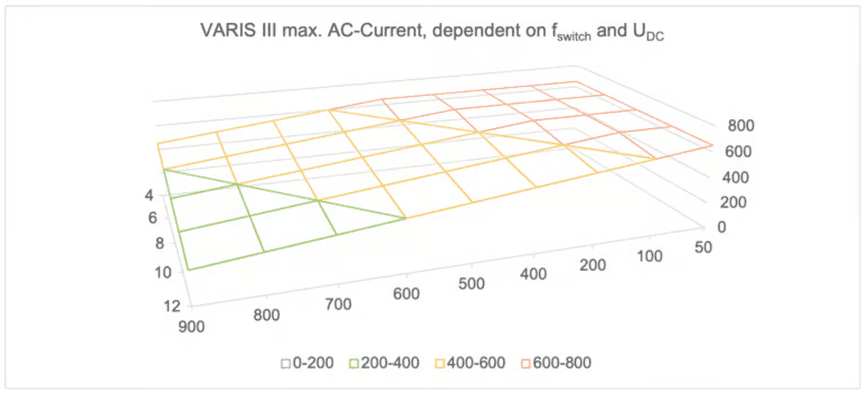
Maximum current is depending on the applied DC voltage and switching frequency. The following diagram illustrates the dependency for example VARIS III:
4.3Position Sensor
4.3.1SIN/COS generator
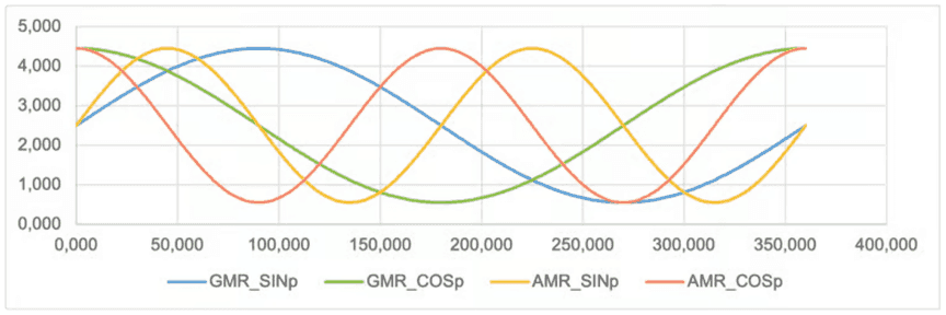
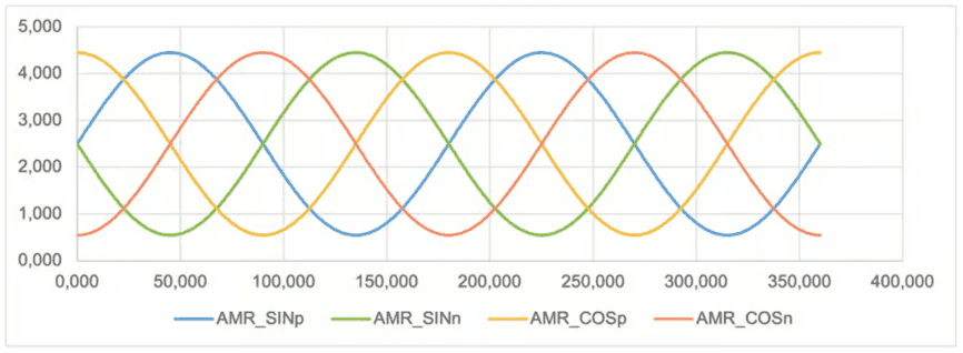
By default, IRS EME comes with an 8 channel SIN/COS signal generator to simulate AMR/GMR position sensors.
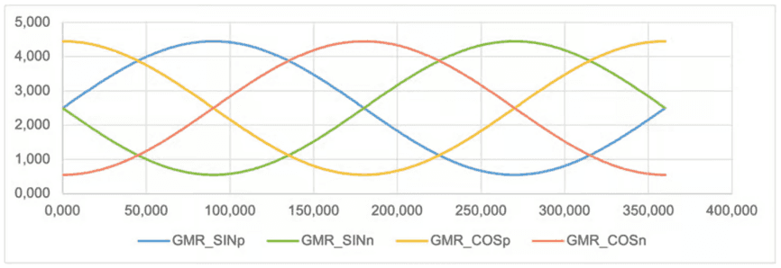
The following pictures illustrate the typical signal levels, depending on the current position in degree. For a clear view, only 4 signals are shown in a single picture. The first one shows non-inverted SIN and COS for GMR and AMR (please note that some inverters use only the GMR-signals):
GMR-signals synchronous to mechanical speed:
AMR-signals synchronous to DOUBLE mechanical speed:
4.3.2Resolver simulation
Optionally, an additional module may be plugged in to simulate resolver position sensors.
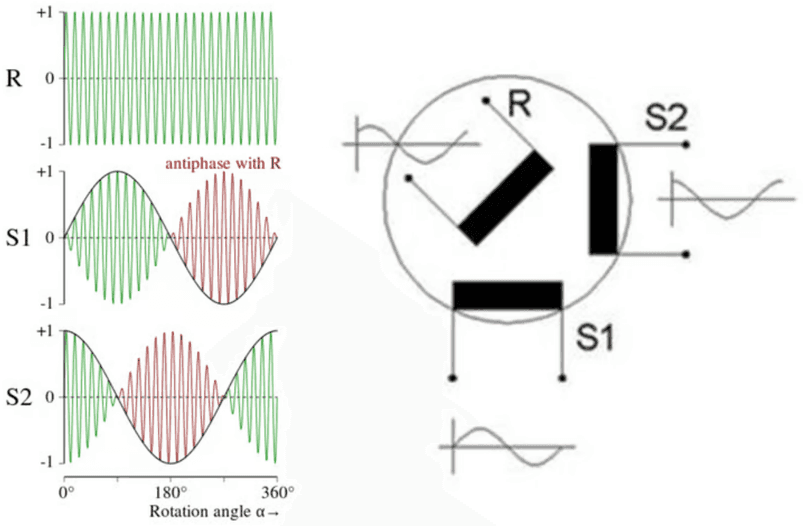
All inputs and outputs are isolated by transformers, as it is the case in real resolver sensors:
- Excitation signal + and - input: generated by the DUT (typ. 10kHz)
- SIN + and SIN – output: modulated by resolver simulator is feedback to the DUT
- COS + and COS – output: modulated by resolver simulator is feedback to the DUT
4.4EME Components and default Device IP Addresses
There are basically two components of measurement equipment, which need to be addressed via Ethernet. These are:
- EME control board
- EME switch and cooling controller
Basically, any IP-address may be configured, but after delivery the following default IP addresses are configured:
| Device | ID / IP-Address | Remarks |
|---|---|---|
| EME Control board | 192.168.222.5 | This device contains the main EME embedded software |
| EME Switch & Cool | 192.168.222.11 | Controller for DC- and discharge-relay, fan, and cooling pump control |
In case, EME is applied in a system with several DUTs, the numbers in the IP-Address are incremented for every test station.
4.5Measurements
4.5.1Voltages, currents, and timing
The following measurements are conducted by the active motor load EME:
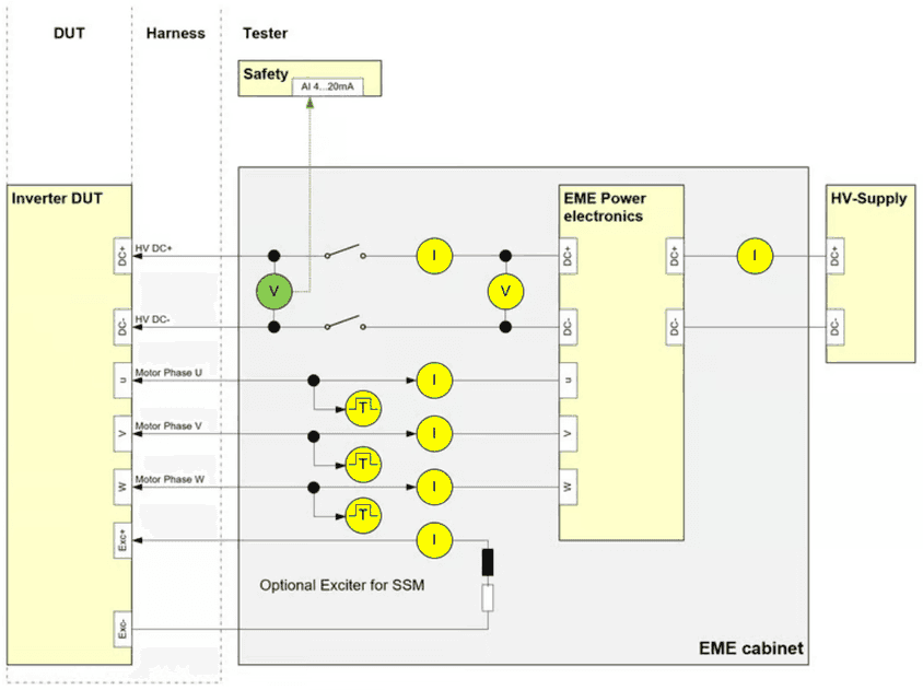
All yellow marked measurements are conducted by the EME controller board, and can be read out by the LabVIEW library via Ethernet. These signals are sampled at a sample-rate of 100kS/s:
- 3x phase current measurement (+-1000A)
- 1x HV DC voltage measurement (0…1000V)
- 1x HV current measurement to DUT (+-600A)
- 1x HV current measurement from HV power supply (+-200A)
- 1x Exciter current measurement (optional) (+-50A)
The voltage measurement after the DC-Main relay is usually evaluated both by safety circuit to detect if there is a hazardous voltage on the DUT and optional additional measurement equipment. EME includes a voltage transducer with an adjustable output signal, marked in green. By default, 4…20mA are output representing the HV voltage at the DUT of 0…1000V.
Finally, motor phases U, V, W PWM timing is monitored with a resolution of 50ns.
4.5.2EME internal temperatures
The following internal temperatures are monitored with a sample rate of approximately 5 S/s.
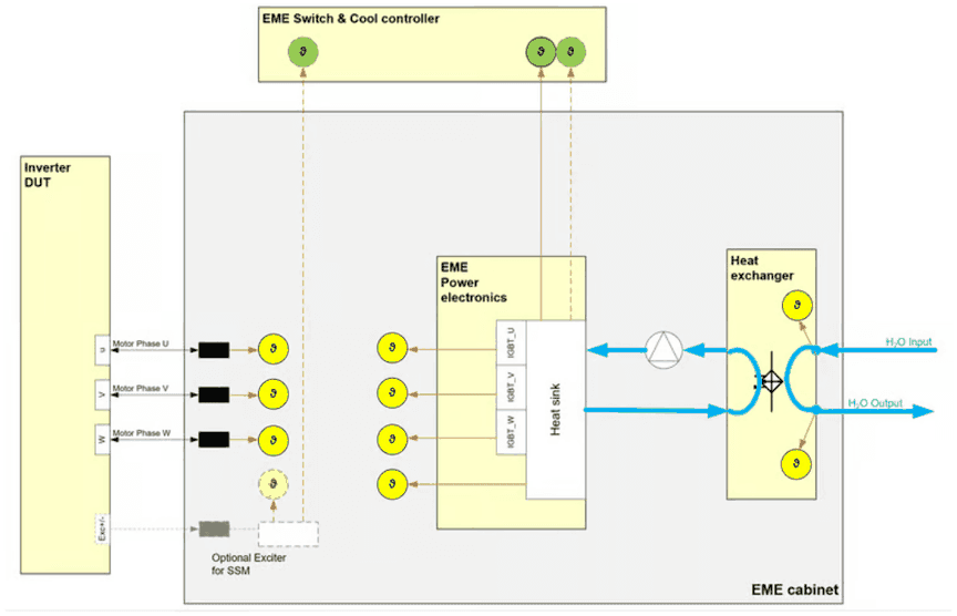
The temperatures must remain below the following maximum values:
| Measured by | Sensor | Description | Maximum Temperature [°C] |
|---|---|---|---|
| EME control board | PT100 | Power stage heat sink | 50 |
| EME control board | IGBT_U | IGBT Phase U (close to heat sink) | 65 |
| EME control board | IGBT_V | IGBT Phase V (close to heat sink) | 65 |
| EME control board | IGBT_W | IGBT Phase W (close to heat sink) | 65 |
| EME control board | Choke_U | Coupling inductance Phase U | 80 |
| EME control board | Choke_V | Coupling inductance Phase V | 80 |
| EME control board | Choke_W | Coupling inductance Phase W | 80 |
| EME control board | Exciter | Optional Exciter resistor for SSM | 70 |
| EME control board | H2O_In | Cooling water inlet | 40 |
| EME control board | H2O_Out | Cooling water outlet | 60 |
| Switch & cool | T VARIS 1 | Power stage heat sink as reference for cooling controller | 50 |
| Switch & cool | T_VARIS 2 / T_Exciter | In case of existing exciter -> exciter resistor, alternatively second T_VARIS |
4.5.3EME cooling and switching controller
The following measurements and controls are conducted by the EME switch and cool unit.
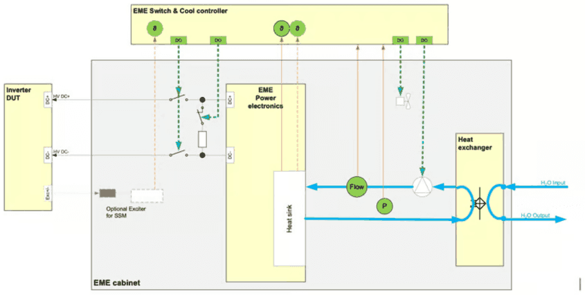
Depending on T_VARIS and T_Exciter the cooling pump is automatically activated and controlled
4.6EME communication
4.6.1Ethernet
Gigabit-Ethernet is the main communication interface which is accessible via the provided LabVIEW library.
4.6.2CAN
Physically available, but currently not implemented in software.
4.7Synchronisation
When EME is operated normally, it synchronizes its output stage to the switching parameters of the DUT. The following chapter describes this synchronization mechanism.
Auto-Synchronization!
4.8Safety interface
4.8.1Standard interface with external safety controller
The following figure illustrates the safety interface:
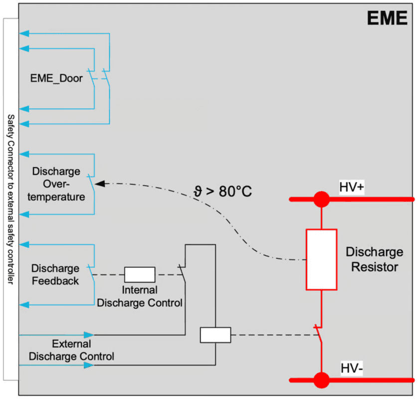
An external safety controller MUST implement the following functionalities:
- It MUST shut down external -Supply immediately in case of
- EME Door Open
- EME Discharge Overtemperature
- EME Discharge Active
- EME-discharge MUST be DE-activated in case of:
- HV-Supply applies a voltage > 20V
- EME-discharge MUST be activated in case of
- Any error
- BUT only when HV-Supply is shut down.
The following table illustrates the different situations, where the discharge control signal is inverted:
| External Safety controller MUST set | HV-Supply | External Discharge control signal |
|---|---|---|
| In case of following status | ||
| EME-Door open | OFF | OFF |
| EME Discharge Overtemperature | OFF | OFF |
| EME Internal Discharge active (indicated by “Discharge feedback” signal) | OFF | ON or OFF; Discharge already activated by EME |
| External Discharge Control active | OFF | ON (no discharge) |
| HV-Voltage >20V applied | ON | ON (no discharge) |
| Isolation failure (independent monitoring, not integrated in EME) | OFF | OFF |
Common safety controllers operate on 24VDC. External Discharge Control signal should be controlled by 24VDC. See the following chapters about electrical parameters and connector pin-out.
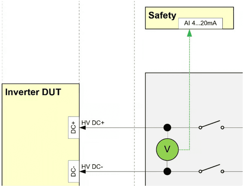
Furthermore, a voltage converter is integrated which can be used by the safety controller to monitor the DUT voltage, and lock doors if voltages >50V are applied.
By default, the voltage converter outputs 4…20mA, which represents 0…1000V at the output to the DUT.
4.8.2Isolation Monitor
An Isolation monitor (e.g. Bender ISO-685) is necessary to monitor the isolation of HV+ and HV- against earth ground, because usually for inverter testing an IT-system is implemented.
In default configuration the HV supply and isolation monitor are not integrated into the emulator. But in case the HV supply is integrated into the emulator cabinet, isolation monitoring is part of the IRS system and must be checked by an integrated safety controller.
4.8.3Integrated safety controller
It is possible to integrate a safety controller depending on customers requirements. This is usually applied, when HV supply is integrated into the emulator cabinet.
There are different options for safety controllers:
- PILZ PNOZ Multi II
- Siemens ET200 safety modules with external CPU
- Wieland safety controller.
- …
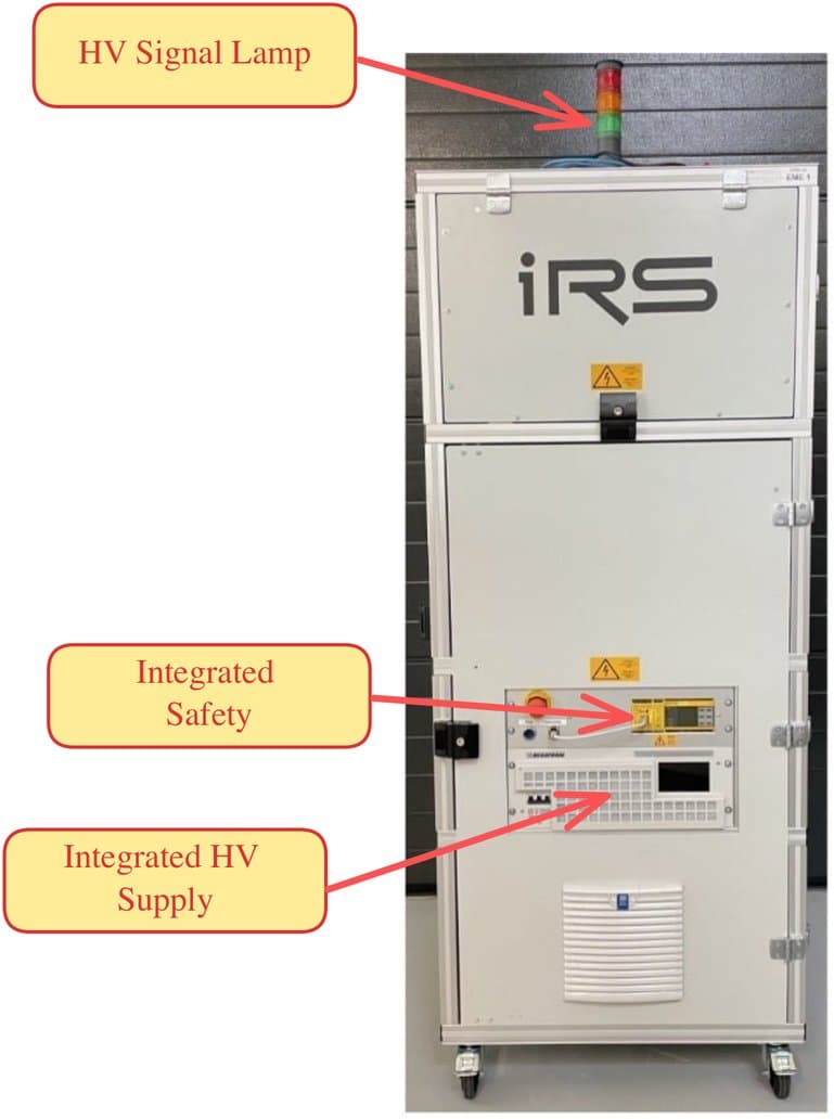
Different options may be individually discussed and integrated. Examples can be found in the following pictures:
4.8.4Example: PILZ or Wieland safety
If any of the safety events occurs, the HV supply is immediately shut down safely and the “Reset” button on the left side will flash in blue color. A single event is stored until the user acknowledges this event by pressing the “Reset button”. The system will remain in safe state until the “Reset” button is pressed by the user.
When the safety event is not present anymore the HV supply is enabled again after acknowledging by the “Reset”-Button.
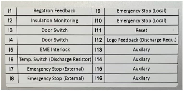
On the indicators on the safety controller the user may read the current status of the safety controller, while the inputs mean the following:
A signal lamp may be mounted on the emulator cabinet to indicate the following situations:
- Green: no failure, no HV voltage -> it is safe to handle DUT
- Red: no failure, HV voltage > 20V -> do NOT touch DUT
- Orange: failure (e.g. emergency stop, isolation failure, door open, …)
An overall safety controller may be used to lock doors in case of applied voltage. This functionality may be integrated by IRS, if required.
4.8.5Example: Siemens ET200 safety
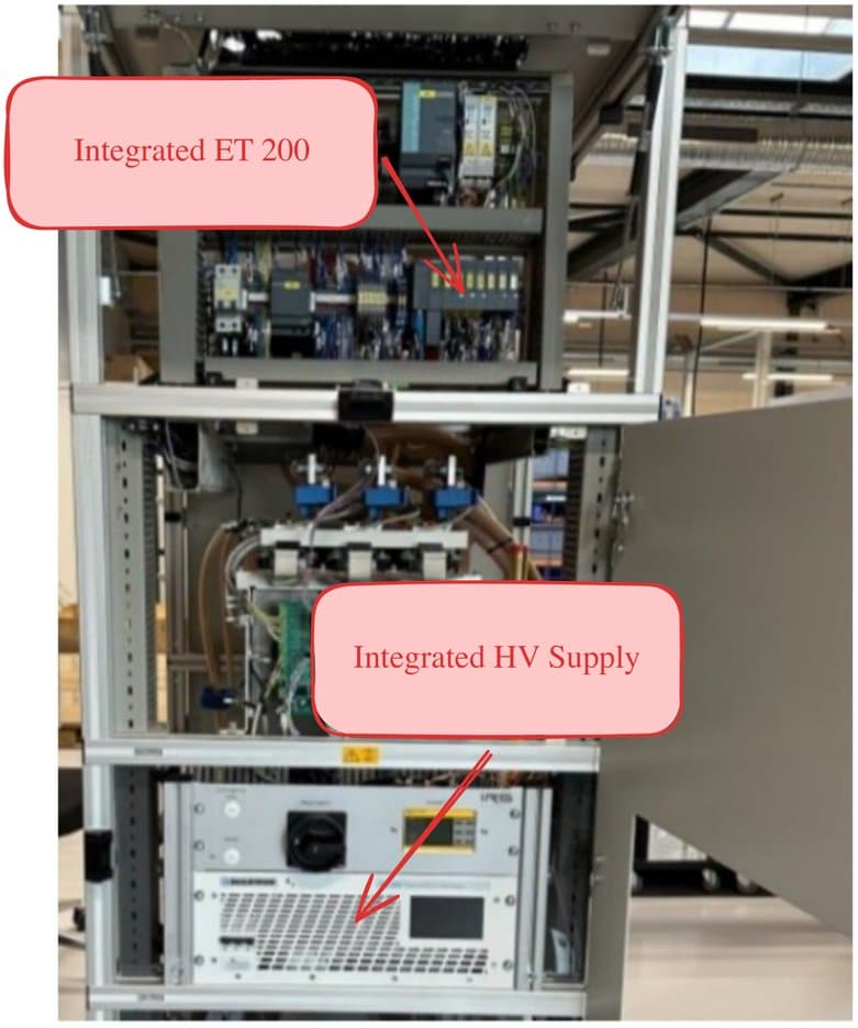
Integrated ET200
With ET200, an external Siemens PLC CPU must be used to implement the safety program. IRS provides an example code that can be used for integration in the PLC CPU.
Integrated HV supply
Please note that with this version the integrator of the PLC software is responsible for the safety of the system. I.e. safe shutdown in any error situation must be handled by the integrator.