The IRS Switching Platform is a standardized solution for signal and load switching. IRS Switching Platform closes standardization gap in automated test environments.
A standardized solution for signal and load switching
| Automated test system | DUT Supply | Control & Measure | Load Simulation |
|---|---|---|---|
| Typical solution | remote controlled Power Supplies | remote controlled devices or PXI, VXI, .. | specific built hardware, switched via dig. I/O |
| Standardization | HIGH | HIGH | LOW -> HIGH with IRS Switching Platform |
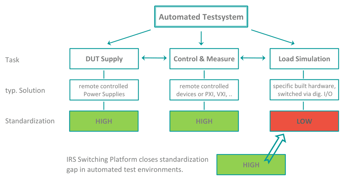
A modular standard solution for switching in test systems
The Switching Platform consists of three standardized parts:
| Topology | Features |
|---|---|
| Mainframe | TCP/IP communication; 4 or 12 slot Backplane; 4x2 ch. Sense Bus |
| Modules | Load Channels (2.. 70A); Matrix 2A (16x4 or 32x6); Custom Card Design |
| Cabling | Standardized Pin Layout; Optimized cable lengths; Modular Fixture Interface |
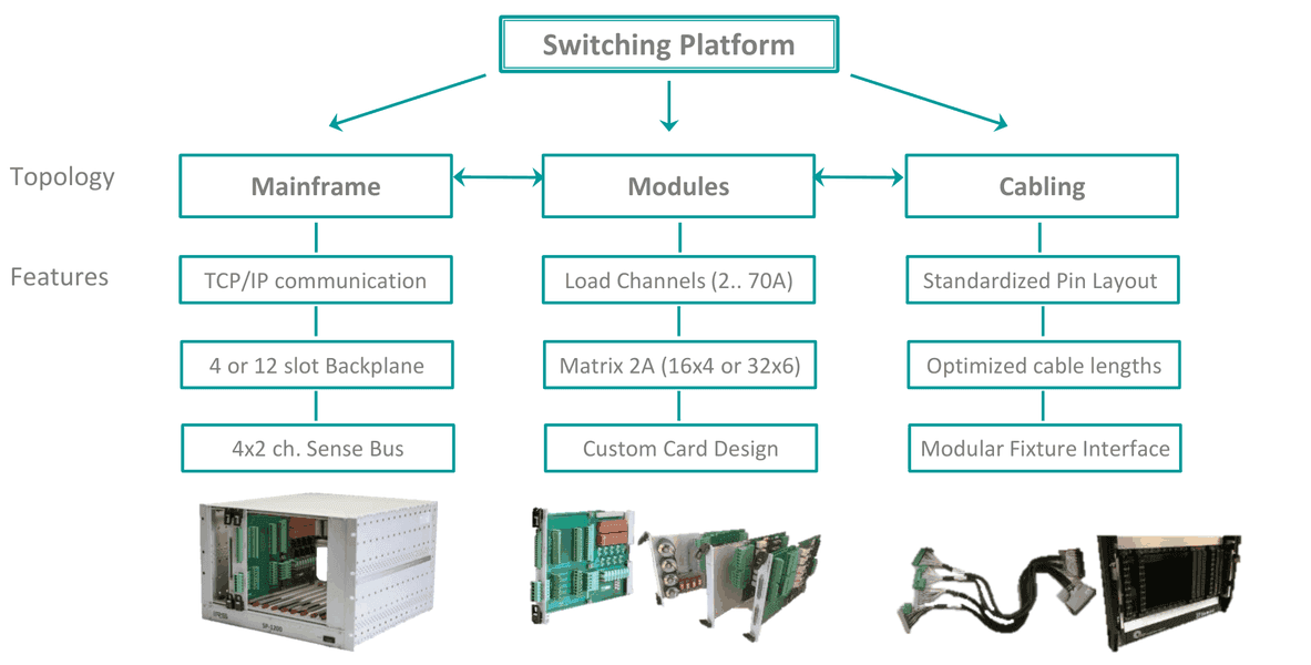
Advantage for test system design:
- effective system planning and ordering process through known components
- easy wiring planning and documentation -> early start of ITA production
- space for load placement available on most SP-Modules, saving 19‘‘-cabinet space for load racks
- future-proof due to modular components -> easy changes, upgrades and extensions
Hardware Overview
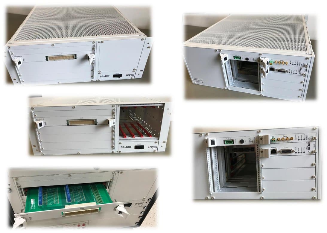
1.1SP-400 Mainframe
- Mainframe size: 4 HU 19‘‘-Rack
- 4 slots for SP-Modules
- 4 slots for additional eurocards (160x100mm)
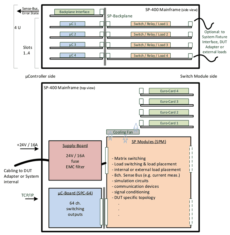
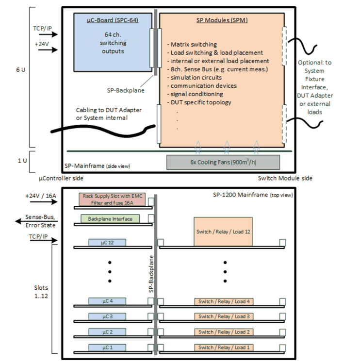
SP Modules (SPM):
- Matrix switching
- Load switching & load placement
- internal or external load placement
- 8ch. Sense Bus (e.g. current meas.)
- simulation circuits
- communication devices
- signal conditioning
- DUT specific topology
- …
Further labels in the schematic:
- µC-Board (SPC-64): 64 ch. switching outputs
- Supply-Board: 24V / 16A fuse, EMC filter
- TCP/IP, +24V / 16A, Sense-Bus, Error State
- Cabling to DUT Adapter or System internal
- Optional: to System Fixture Interface, DUT Adapter or external loads
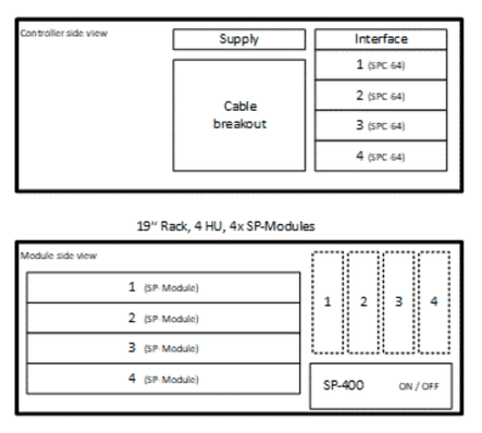
1.2SP-1200 Mainframe
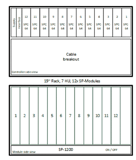
- Mainframe size: 7 HU 19‘‘-Rack
- 12 slots for SP-Modules
- 6 fans for load cooling
1.2.1Front and rear view
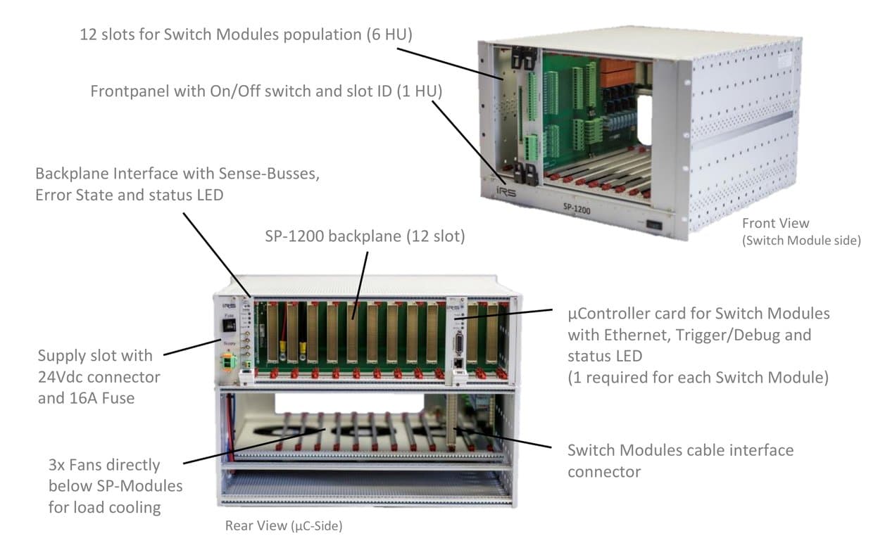
Front View (Switch Module side):
- 12 slots for Switch Modules population (6 HU)
- Frontpanel with On/Off switch and slot ID (1 HU)
- 3x Fans directly below SP-Modules for load cooling
Rear View (µC-Side):
- Backplane Interface with Sense-Busses, Error State and status LED
- Supply slot with 24Vdc connector and 16A Fuse
- µController card for Switch Modules with Ethernet, Trigger/Debug and status LED (1 required for each Switch Module)
- SP-1200 backplane (12 slot)
- Switch Modules cable interface connector
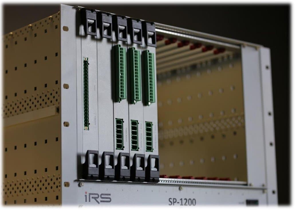
1.2.2Rack Supply Slot
SP-1200 Power Supply requirements: 24Vdc, max. 16A
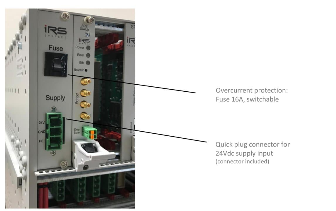
- Overcurrent protection: Fuse 16A, switchable
- Quick plug connector for 24Vdc supply input (connector included)
1.2.3Backplane Interface Card
SP-1200 Backplane signal connectivity to external devices and systems.
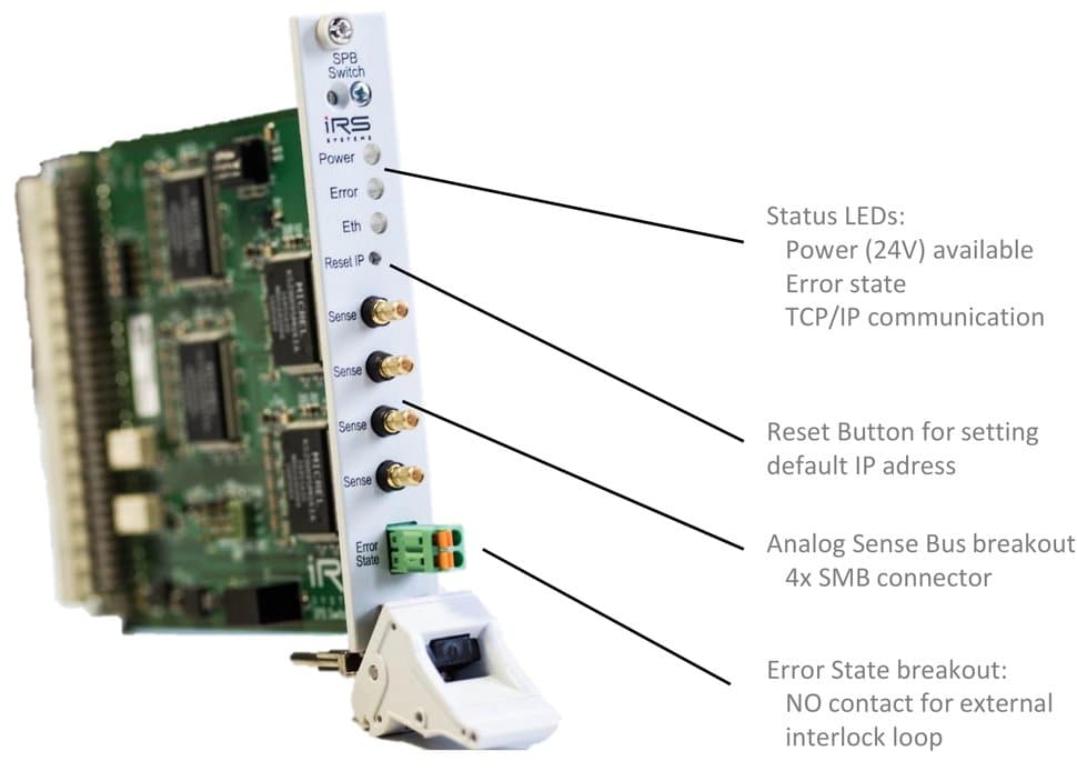
- Status LEDs: Power (24V) available, Error state, TCP/IP communication
- Reset Button for setting default IP address
- Analog Sense Bus breakout: 4x SMB connector
- Error State breakout: NO contact for external interlock loop
1.2.4Switch Module µController Card
- 64x relay driver outputs (switching to GND; 300mA/ch; 10A total)
- 32x analog input channels (4x8 MUX; 12bit; 3,3V)
- 8x Dig. I/O configurable
- 1x CAN, 1x SPI communication
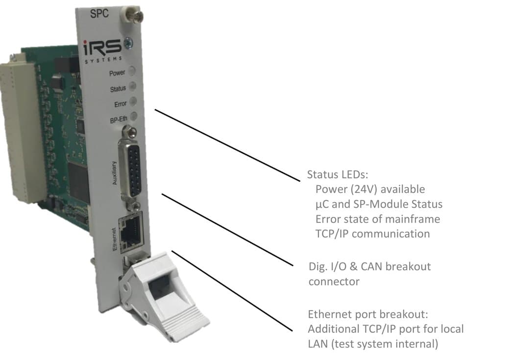
- Status LEDs: Power (24V) available, µC and SP-Module Status, Error state of mainframe, TCP/IP communication
- Dig. I/O & CAN breakout connector
- Ethernet port breakout: Additional TCP/IP port for local LAN (test system internal)
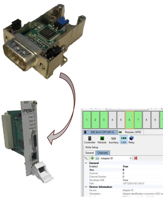
1.2.5Programmable ID Module
- Small CAN communication based ID module
- EEPROM for customer data read/write access
- Fixed worldwide unique ID
- Direct connect to SPC-64 Auxiliary connector read & write via TCP/IP of SPC-64
- Easy configuration via SP Editor SW
Use Cases:
- placed in sub components like DUT Adapters or fixture interface box for automated identification
- system or adapter related data transfer (e.g. calibration data, contacting counters, ..)
1.3SP-1200 Module Portfolio (Q1/22)
1.3.1Loadcard Modules -LC
| Module | I/U Rating | Power Bus | Channels | Diagnostics | Features |
|---|---|---|---|---|---|
| SPM-700401-LC-MF | 70A 60V | -- | 4x1 ch. | current loop | 4 MOSFET switches form A, fuse, I-Sense, theta-Sense |
| SPM-300602-LC | 30A 60V | -- | 6x2 ch. | current loop | Fuse, I-Sense, theta-Sense |
| SPM-100802-LC | 10A 60V | 4 | 8x2 ch. | -- | Fuse, I-Sense, dual-/single channel config, DMM current measurement |
| SPM-100802-LC-MF | 10A 60V | 4 | 8x2 ch. | -- | MOSFET switches, fuse, I-Sense, dual-/single channel config, DMM current measurement |
| SPM-061601-LC | 6A 150V | -- | 16x1 ch. | current loop | 16 form A contacts with load breakout pcb, DMM current measurement |
| SPM-061601-LC-E02 (new) | 6A 60V | 4 | 12x2 ch. | current loop | Dual load extension for 12 channels switchable to 4x power busses, integrated shunt: current measurement ranges 1A, 2.5A, 6A configurable |
| SPM-026401-LC | 2A 60V | 4 | 64x1 ch. | Readback | 64 form A contacts with load config pcb |
| SPM-022404-LC | 2A 60V | 4 | 24x4 ch. | readback | 24x4 topology (1 channel to 4 loads), 4x piggyback pcb‘s for loads, current transducers optional |
1.3.2Matrix Modules -MX
| Module | I/U Rating | Columns | Rows | Diagnostics | Features |
|---|---|---|---|---|---|
| SPM-023206-MX | 2A 60V | 6 | 32 | readback | Topology 32 rows (2A) to 6 columns (10A), each row fused, breakout connector |
| SPM-021604-MX | 2A 60V | 4 | 16 | readback | Topology 16 rows (2A) to 4 columns (10A), each row fused, breakout connector |
1.3.3Fault Simulation Modules -FS
| Module | I/U Rating | Topology | Diagnostics | Features |
|---|---|---|---|---|
| SPM-300802-FS (new) | 30A 60V | 8 Ch. / 2x Fault Bus | current loop | Connects 8x DUT pins (30A each) to 2x 40A fault busses (typ. Vcc and GND), LED indicators |
| SPM-020802-FS-D-FI (new) | 2A 60V | 8x2 Ch. / 2x Fault Bus | current loop | Connects 8 differential DUT pins (2A each) to 2x 40A fault busses (typ. Vcc and GND). Additional 2x MOSFET fast interrupter switches 2A and 40A for Power ON/OFF scenarios |
| SPM-022002-FS (new) | 2A 60V | 20 Ch. / 2x Fault Bus | current loop | Connects 20x DUT pins (2A each) to 2x 40A fault busses (typ. Vcc and GND) |
1.3.4Other Modules
| Module | I/U Rating | Topology | Diagnostics | Features |
|---|---|---|---|---|
| SPM-014002-HV | 1A 1000V | 40 Ch. | -- | High voltage card with configurable topology: 4x10 ch., dual 2x10 ch. or 2x 20 ch. |
| SPM-SYS-001 | -- | 8x2 Ch. | -- | Aux power supply monitoring (5V, 12V, 24V), 16x Dig. IN, 12x Dig. Out, 8x diff. Signal switching |
| SPM-1000201-ME-CMM | 100A 32V | 2x1 Ch. | current loop | 2x calibrated autoranging current measurement channels from µA-100A |
1.3.5Stand Alone Modules -STA
| Module | I/U Rating | Topology | Diagnostics | Features |
|---|---|---|---|---|
| SPM-DRV-001-STA (new) | 16A 48V | 32x Output 2.5A, 50V; 32x Output 0.3A, 30V; 32x LVTTL Input 30V | readback coupling (SW), LED display | 64x open drain outputs (2.5A/0.3A) for high power switching; 16A max. total current; 32x Dig. Inputs, via SW configuration as status readback for switching state validation. Additional features: 8x NO relays 2A, 60V; 2x Temperature sensor inputs; cooling fan and error state contact |
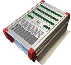
Switching Platform Stand Alone Modules:
- stand alone solutions for distributed switching tasks (no SP mainframe required)
- typical formfactor: small aluminium housing with LxWxH ~190x125x60mm
- connectivity: TCP/IP port of system controller, supply voltage (e.g. 24Vdc), all other specific hardware (e.g. high power relays, control LEDs, ..)
- full integration in SP software (configuration, setting, alias names, debugging windows, ..)
- easy integration as Add On in each existing SP topology (e.g. connect to unused SPC-64 TCP/IP socket)
- note: SPM-…-STA products have different formfactor and are not designed for use inside SP-Mainframes
1.4SP Modules
1.4.1SPM-700401-LC-MF (MOS-FET)
- 4x channels: 70A continuous ON; 85A max. 40 sec ON / 80 sec OFF; 100A max. 20 sec ON / 50 sec OFF
- Current measurement app. 1% (±85A)
- Current and temperature monitoring
- PCB Temp. vs. Current (3 fans on):
| Current | PCB Temp. / time |
|---|---|
| 70A | 95°C / 30 min. |
| 85A | 60°C / 30 sec.; 80°C / 40 sec; 95°C / 60 sec |
| 100A | 60°C / 10 sec; 80°C / 20 sec |
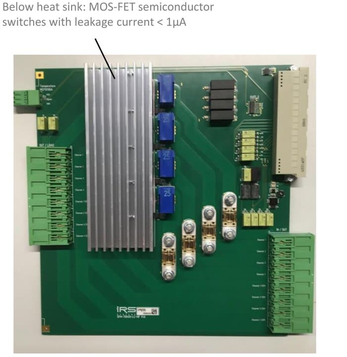
Below heat sink: MOS-FET semiconductor switches with leakage current < 1µA.
Current transducers app. 1% precision, offset referenced. Sensitivity: 25mV/A; Vout: -2,125V .. 2,125V (= -85A..85A).
Power supply switching example
SPM-700401-LC-MF used for switching power supply outputs (up to 70A) to DUT (example configuration).
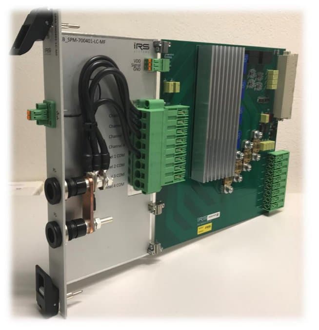
Using two MOSFET channels parallel would allow switching of app. 150A.
Schematic
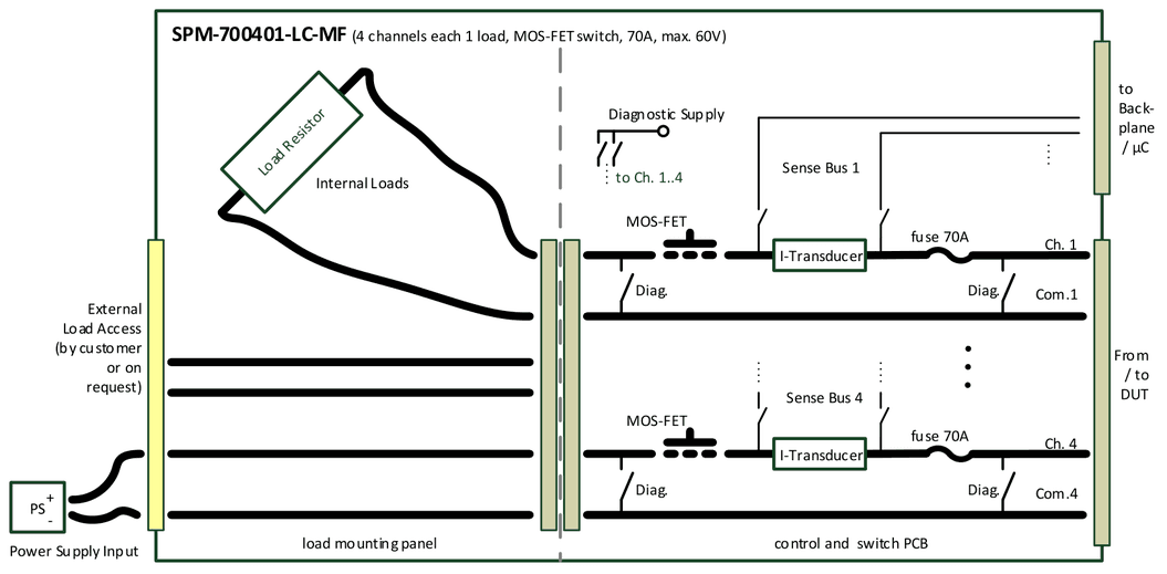
- 4 Channels, each 70 A, 60V
- Integrated current transducers (app. 1%), output voltage connectable to Sense-Bus 1..4; current value also via communication (reduced precision)
- Onboard diagnostic (self test: relay state open/close, current transducers function)
- Overcurrent and overtemperature monitoring -> channel switch to open
- Internal load placement and external load breakout
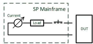
Load scenarios
Switch high current load between DUT pins with integrated current measurement (app. 1%):
Switch external placed high current load between DUT pins with integrated current measurement (app. 1%):
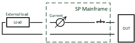
Connect high current power supply directly to DUT with integrated current measurement (app. 1%):
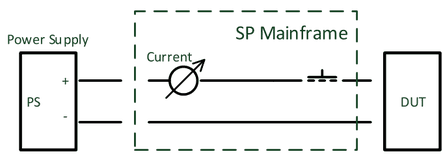
Hot switching possible due to MOSFET switches.
1.4.2SPM-300602-LC
- 6x2 channels 30A (40A max. 60 sec)
- Current measurement app. 1% (±40A)
- Current and temperature monitoring
- Internal diagnostic
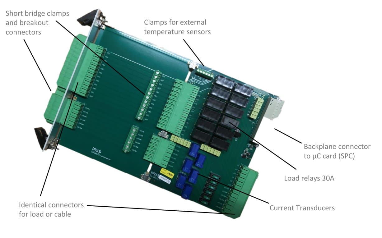
Labeled components: Short bridge clamps and breakout connectors; Clamps for external temperature sensors; Identical connectors for load or cable; Load relays 30A; Current Transducers; Backplane connector to µC card (SPC).
SPM-300602-LC-E: Schematic
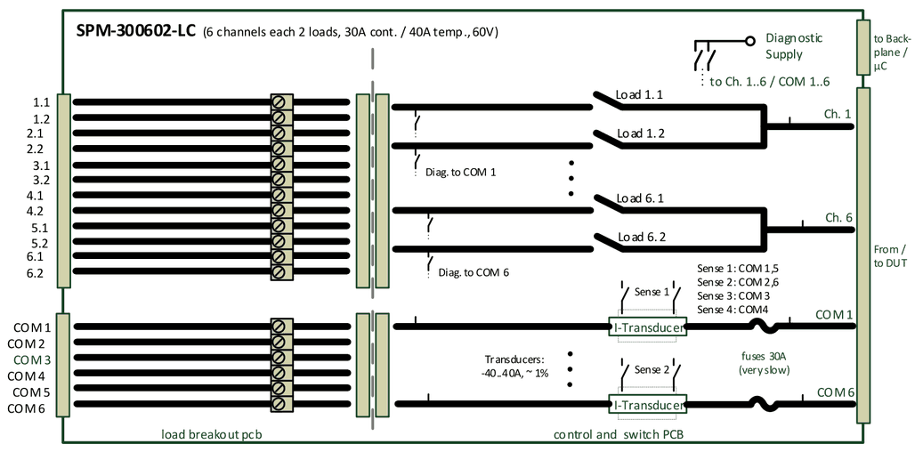
- 6x2 Channels, each 30 A (40 A temporary app. 1 minute), 60V
- Integrated current transducers (app. 1%), output voltage connectable to Sense-Bus 1..4; current value also via communication (reduced precision)
- Onboard diagnostic (self test: relay state open/close, fuse, current transducers function)
- Overcurrent and overtemperature monitoring -> channel switch to open
- Internal load placement and external load breakout
Transducers: -40..40A, ~ 1%. Sense 1: COM 1,5; Sense 2: COM 2,6; Sense 3: COM 3; Sense 4: COM4.
SPM-300602-LC-P: Schematic
SPM-300602-LC with option –P = load mounting panel.
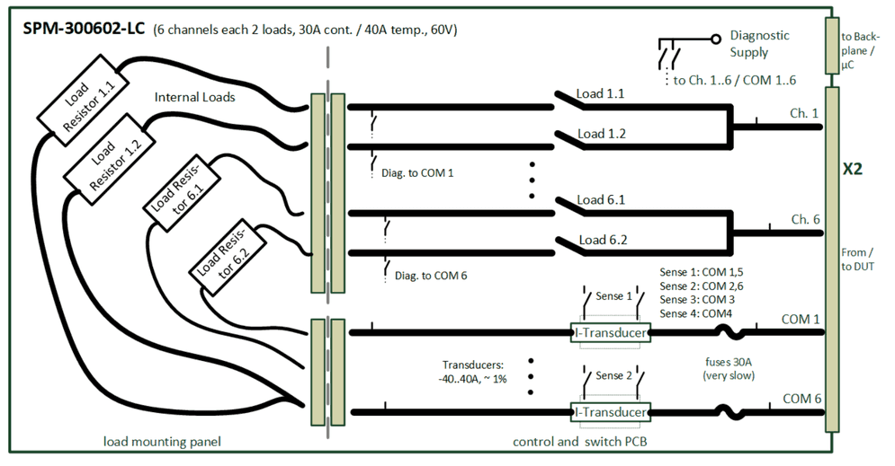
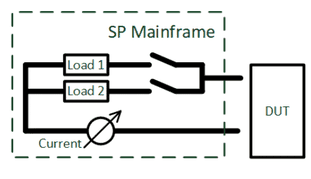
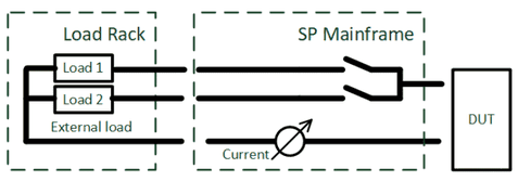
Load scenarios
Switch 2 different high current loads between DUT pins with integrated current measurement (app. 1%):
Switch 2 different external placed high current loads between DUT pins with integrated current measurement (app. 1%):
Connect high current power supply directly to DUT with integrated current measurement (app. 1%):
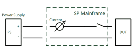
Hot switching not possible.
1.4.3SPM-100802-LC
- 8x2 channels 10A, 60V, fused
- Each channel configuration as dual load or single channel
- Current measurement via shunt, current transducer or in-line DMM
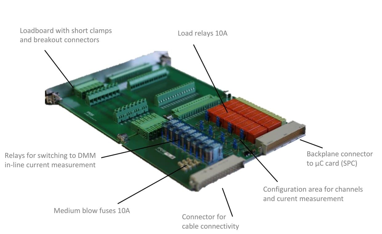
Labeled components: Loadboard with short clamps and breakout connectors; Load relays 10A; Relays for switching to DMM in-line current measurement; Medium blow fuses 10A; Connector for cable connectivity; Configuration area for channels and current measurement; Backplane connector to µC card (SPC).
Current measurement
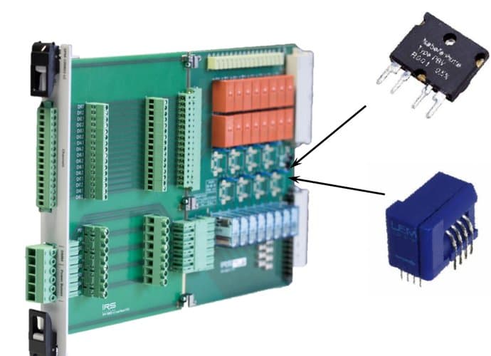
Standard shunts: 25mOhm, 50mOhm, 1Ohm, 10Ohm (0.5..0.05%); 3W max. continuous power; other values on request.
Current Transducer: -12A .. 12A, ~1% precision, 200kHz; Vout offset referenced; Sensitivity: 104,2mV/A; Vout: -1,250V .. 1,250V (= -12A..12A).
Each of the 8 load channels can be configured with shunt or current transducer. Standard delivery state is blank (no shunts or current transducers). On request also mounted or separate shunts or CT-Modules possible.
Schematic
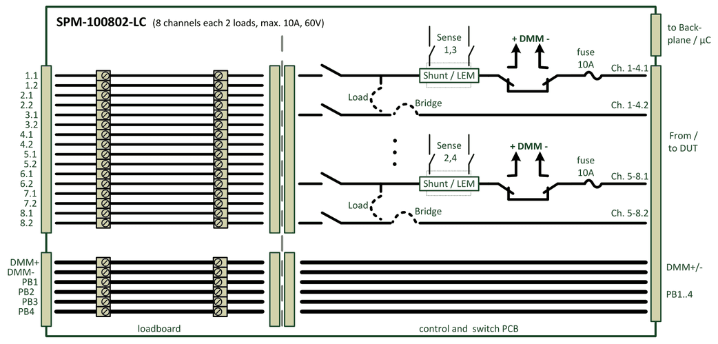
- 8x2 Channels, each 10 A, 60V, 4x Power Bus max. 18A
- Shunt or current transducers, output voltage connectable to Sense-Bus 1..4; 4 parallel current measurements: ch.1..4 to Sense 1 & 3 and ch. 5..8 to Sense 2 & 4
- Direct DMM in-line current measurement on each channel
- Loadboard with breakout connectors and clamps for shorts and smaller loads
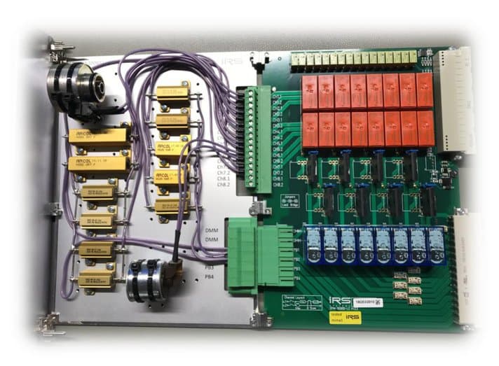
Load configuration example
SPM-100802-LC used for specific load configuration including original motor inductors (example configuration).
1.4.4SPM-026401-LC
- 64x channels form A, 2A, 60V
- 4x power bus lines 10A
- Relay state readback via 2nd contact
- Loadboard for easy load configuration and breakout connector
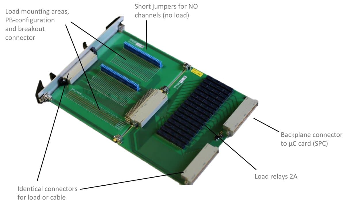
Labeled components: Load mounting areas, PB-configuration and breakout connector; Short jumpers for NO channels (no load); Identical connectors for load or cable; Load relays 2A; Backplane connector to µC card (SPC).
Schematic
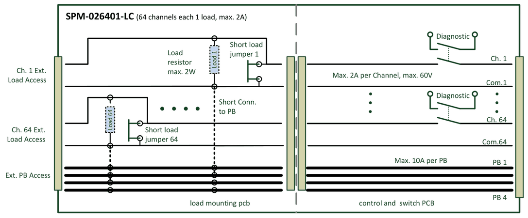
- 64 Channels each 2 A, 60V & 4x Power Bus Lines, 10A each
- Relay switching state monitoring via 2nd contact
- Loadboard for internal loads mounting and external load access
- including 64 short jumpers and external cable side connector
Load scenarios
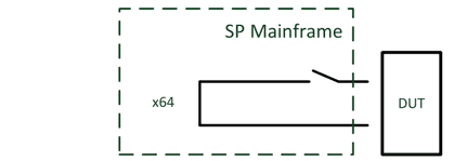
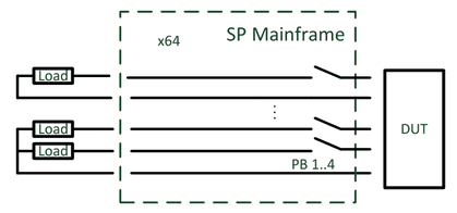
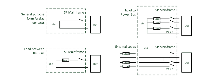
Use all 64 channels as Form A (SPST) relay contacts with max. current 2A (standard delivery state of all 64 jumpers on loadboard):
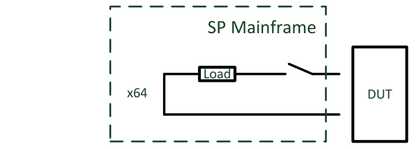
Switch internal placed loads between DUT pins:
Switch internal placed loads to 4x Power Bus lines (max. 10A per PB line):
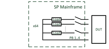
Switch external placed loads between DUT pins or to 4x Power Bus lines (max. 10A per PB line):
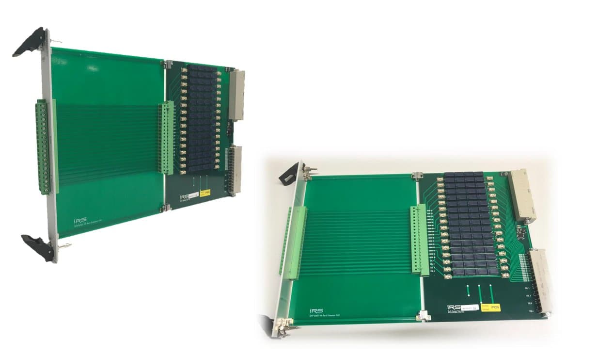
1.4.5SPM-021604-MX
- 16x4 matrix crosspoints, 2A, 60V
- 4x column lines for max. 10A
- 16x row lines 2A, fused
- Relay state readback via 2nd contact
- breakout connectors rows/ & columns
Schematic
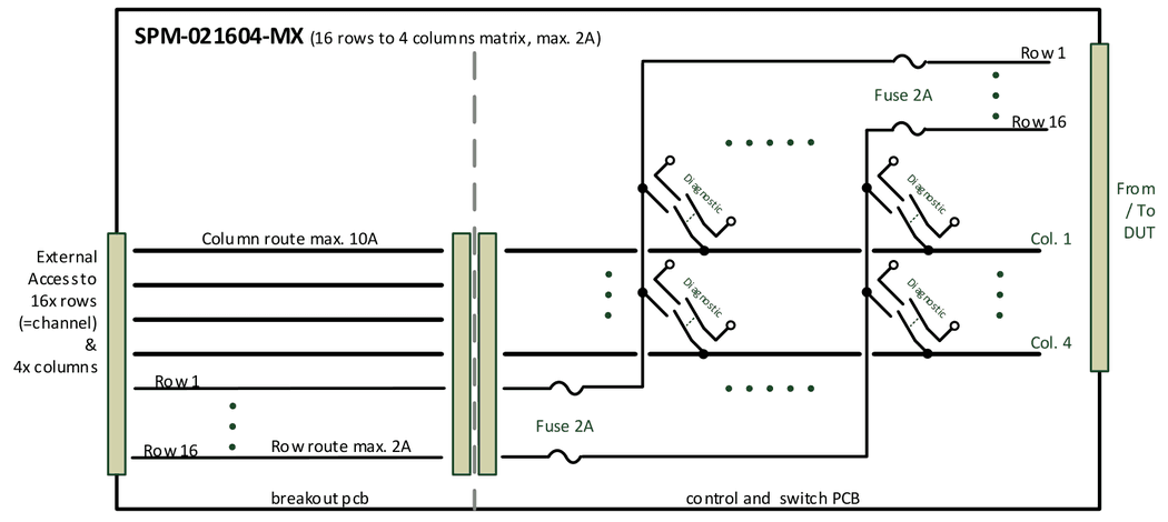
- Matrix 16x4 topology (16 rows/channels to 4 columns)
- Each row/channel max. 2A, 60V, incl. fuse
- Each column max. 10A
- Relay switching state monitoring via 2nd contact
- Loadboard for external access to channels and rows
- including external cable side connector
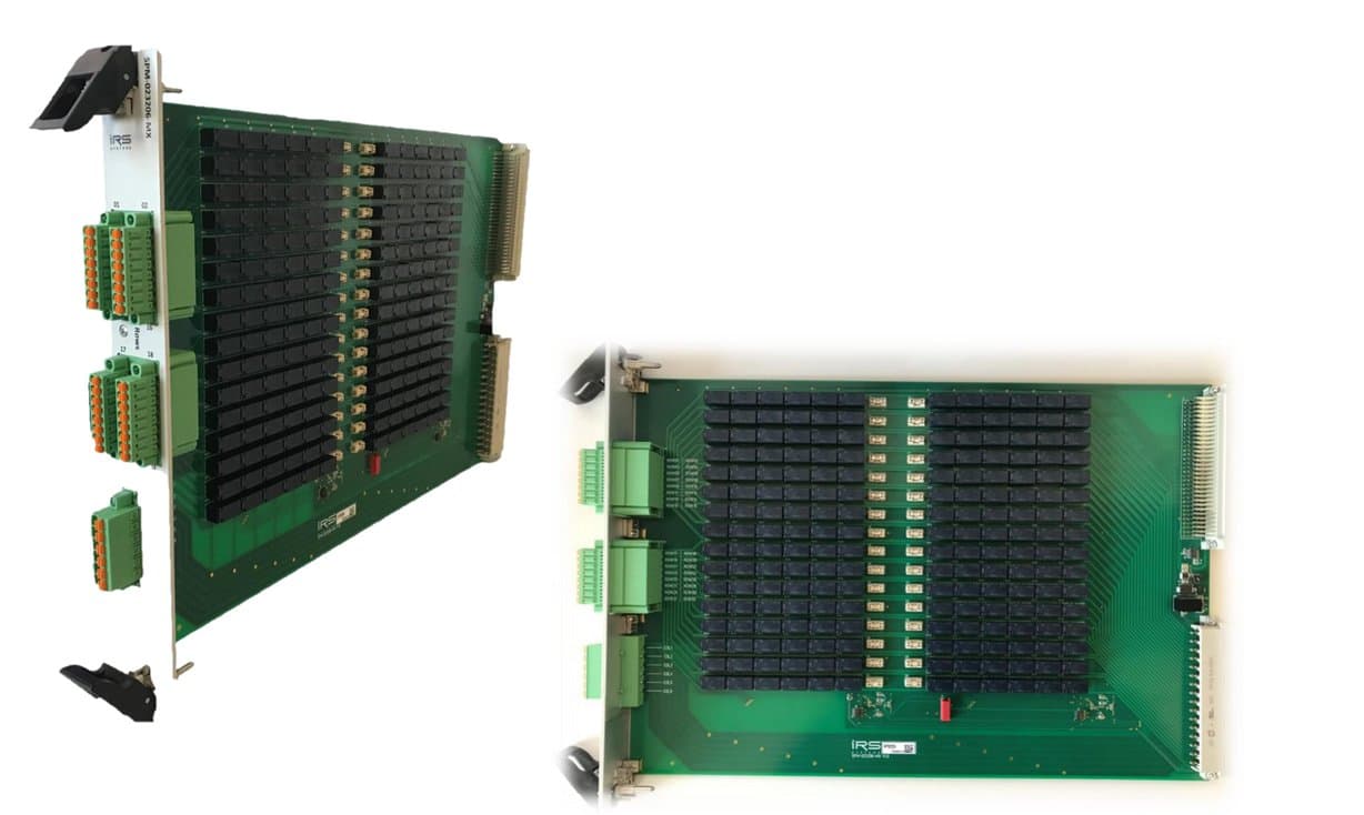
1.4.6SPM-023206-MX
- 32x6 matrix crosspoints, 2A, 60V
- 6x column lines for max. 10A
- 32x row lines 2A, fused
- Relay state readback via 2nd contact
- breakout connectors rows/ & columns
Schematic
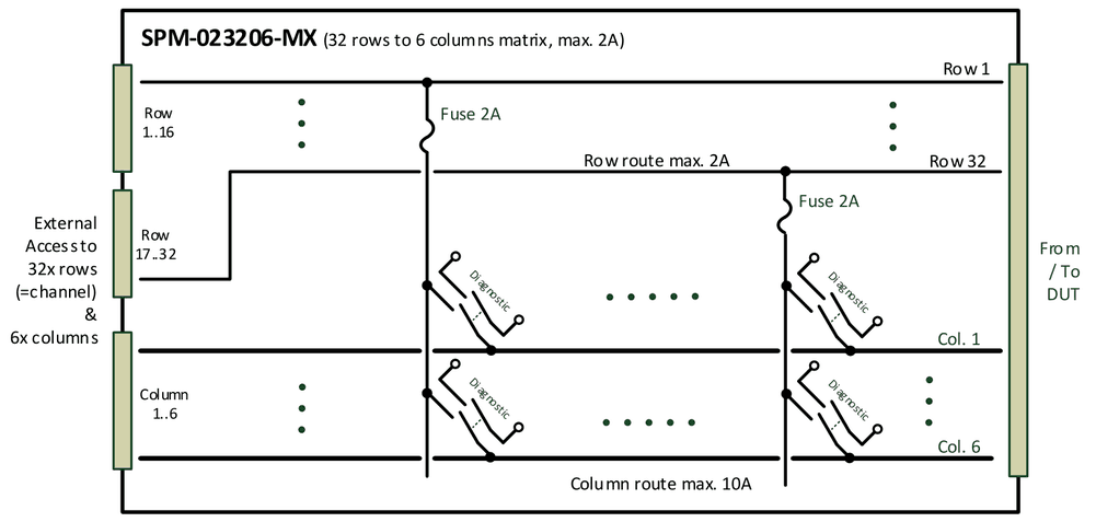
- Matrix 32x6 topology (32 rows/channels to 6 columns)
- Each row/channel max. 2A, 60V, incl. fuse
- Each column max. 10A
- Relay switching state monitoring via 2nd contact
- Breakout connectors for external access to channels and rows
- including external cable side connector
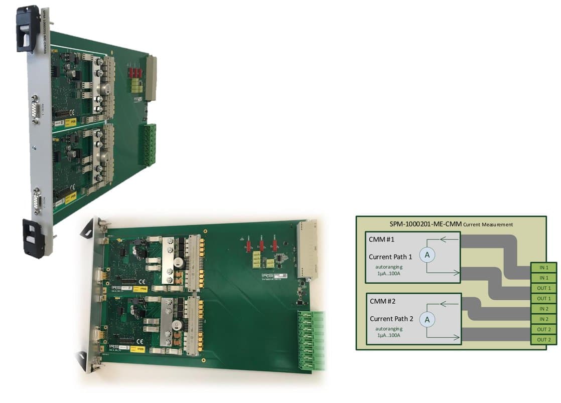
1.4.7SPM-1000201-ME-CMM
- 2x CMM-III or CMM-IV on a SP-Module carrier
- autoranging current measurement from 1µA- 100A on 2 channels
- expandable to max. 8 CMM‘s
- internal diagnostic via loop current
- standard factory or DAkkS calibration
- Full SP-SW support: read current values via TCP/IP commands
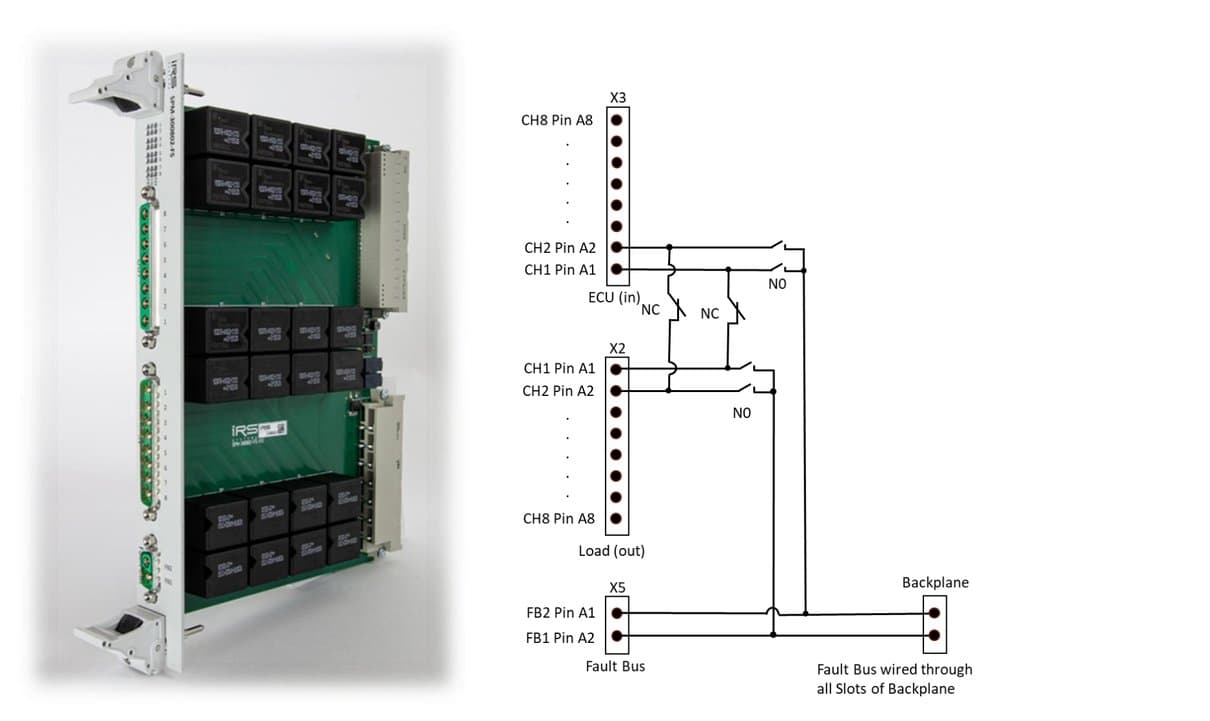
1.4.8SPM-300802-FS
- 8x fault simulation channels 30A, 60V
- 2x fault bus 40A (60A temp.)
- LED indicators, internal diagnostic
- high power breakout connectors
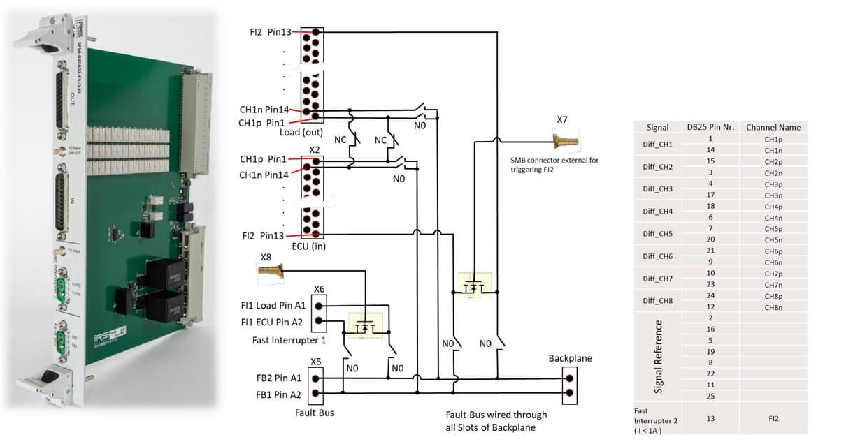
1.4.9SPM-020802-FS-D-FI
- 8x differential channels 2A, 60V
- 2x fault bus 40A (60A temp.)
- 2x fast interrupter (MOSFET, 2A, 40A)
- Internal diagnostic
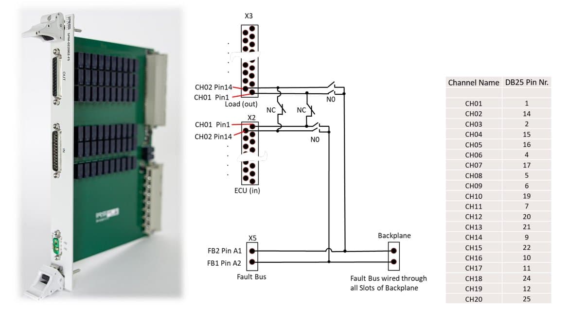
1.4.10SPM-022002-FS
- 20x fault simulation channels 2A, 60V
- 2x fault bus 40A (60A temp.)
- Internal diagnostic
1.4.11SPM-DRV-001-STA
- 32x Open drain outputs 2.5A, 50V
- 32x Open drain outputs 0.3A, 30V
- 32x Dig. Inputs LVTTL max. 30V
- 8x relays form A (normally open) 2A
- 2x temperature sensor inputs
- 16A total current rating
- external fan output
- Error State contact (normally closed)
- Internal diagnostic & LED indicators
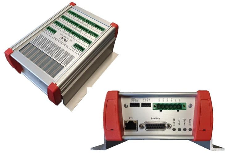
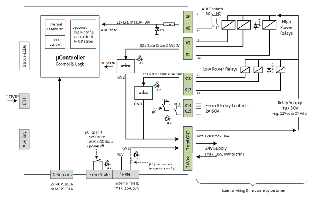
Switching of high power relays and contactors for high power requirements: 32x 2.5A/50V & 32x 0.3A/30V & total current 16A.
Automated readback of contactors AUX contacts to ensure correct switching states: Dig. IN and Dig. OUT can be linked via SW configuration, error raised if AUX state does not match.
Compact stand alone module, TCP/IP communication, distributed topologies.
Block diagram
1.5SP-1200 System Integration
System Integration 19‘‘-Cabinet, 38HU:
- 2x PXI Chassis each 18 slot
- 2x SP-1200 Mainframe each 12 slot
- 4x PS Channels (1x 1.500W, 4x 100W)
- Rack for additional HW (3HU)
- optional UPS or additional PS
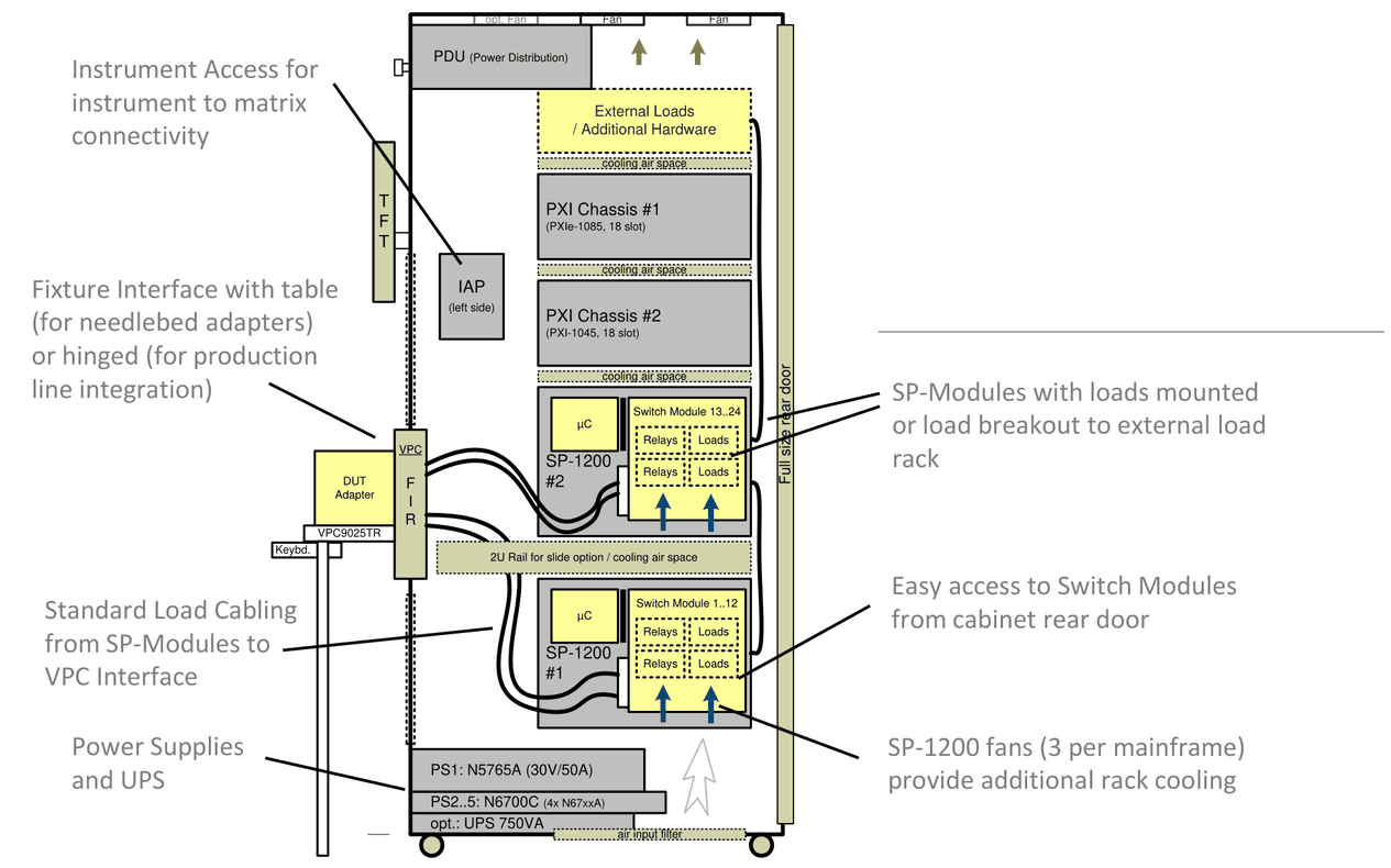
- Instrument Access for instrument to matrix connectivity
- Fixture Interface with table (for needlebed adapters) or hinged (for production line integration)
- Standard Load Cabling from SP-Modules to VPC Interface
- Power Supplies and UPS
- SP-Modules with loads mounted or load breakout to external load rack
- Easy access to Switch Modules from cabinet rear door
- SP-1200 fans (3 per mainframe) provide additional rack cooling
1.6TCP/IP Topology
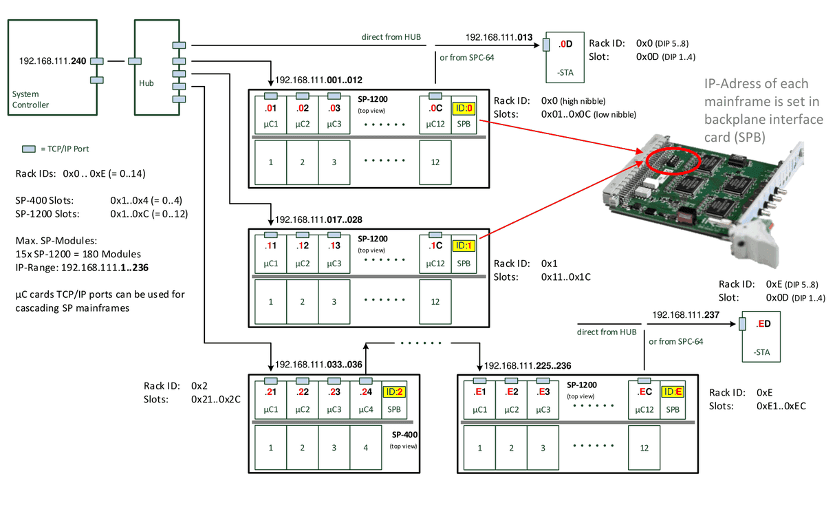
- Rack IDs: 0x0 .. 0xE (= 0..14)
- SP-400 Slots: 0x1..0x4 (= 0..4)
- SP-1200 Slots: 0x1..0xC (= 0..12)
- Max. SP-Modules: 15x SP-1200 = 180 Modules
- IP-Range:
192.168.111.1..236 - µC cards TCP/IP ports can be used for cascading SP mainframes
- IP address of each mainframe is set in backplane interface card (SPB)
Further labels in the diagram:
- System Controller:
192.168.111.240 - -STA
192.168.111.013: direct from HUB or from SPC-64; Rack ID: 0x0 (DIP 5..8), Slot: 0x0D (DIP 1..4) - -STA
192.168.111.237: direct from HUB or from SPC-64; Rack ID: 0xE (DIP 5..8), Slot: 0x0D (DIP 1..4)
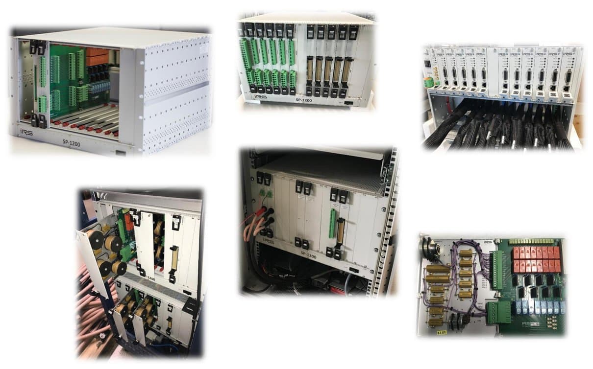
1.7SP-1200 Gallery
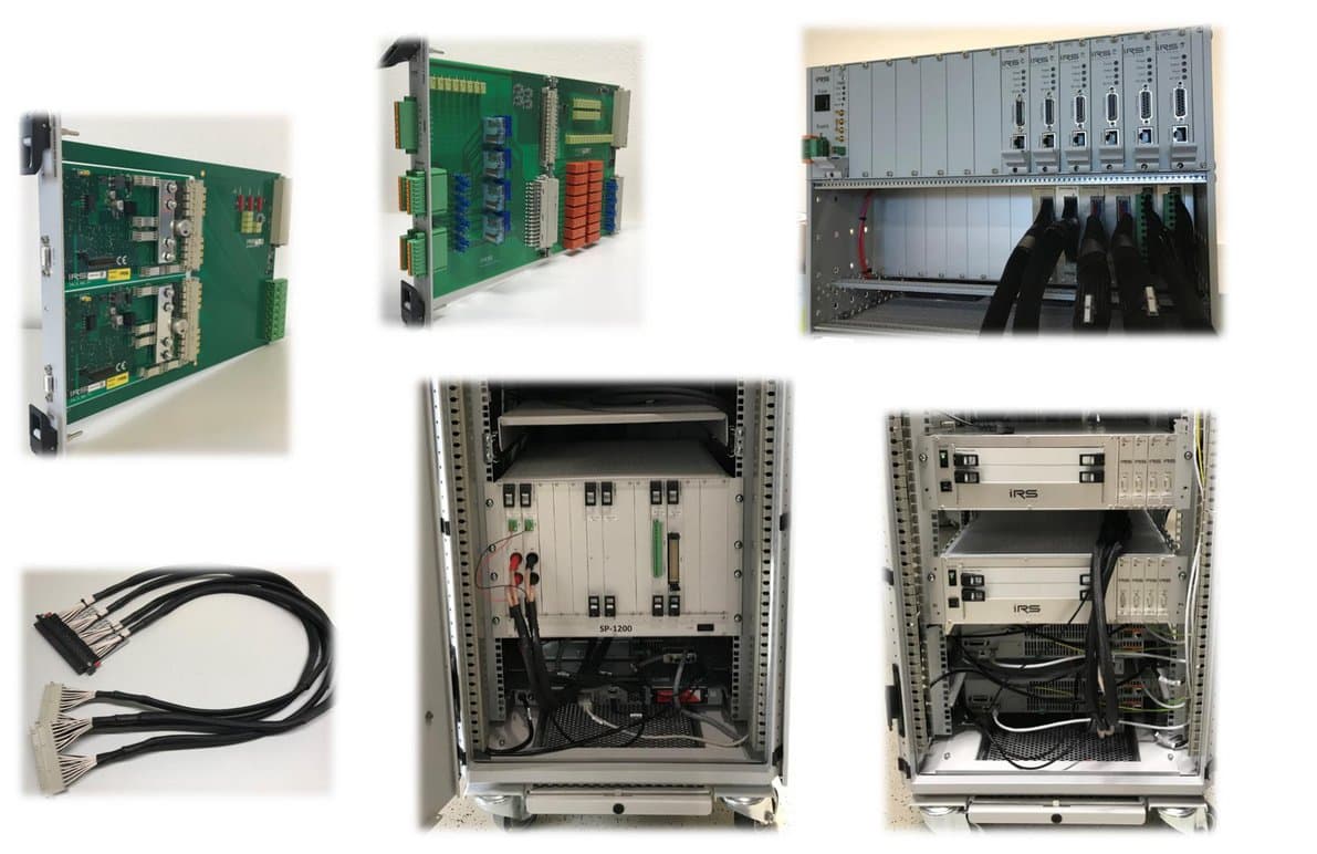
Datasheet SP-1200
SP-1200 Mainframe – IRS product 121466 SP-1200, Switching Platform Mainframe 12 slot, v2; hardware version 2.0.
2.1General Description
The IRS Switching Platform provides standardized, modular and scalable integration of switching tasks in automated test systems. Typical tasks are load switching, power matrix switching, communication distribution, load path current measurement and signal conditioning. IRS provides a portfolio of modules for that switching functionality, further modules can be developed and built by IRS GmbH on request.
The SP-1200 Mainframe is a 7HU 19‘‘-Rack that controls the switching states of up to 12 Plug-In modules with size 6HU and 6HP standard width.
The Switching Platform Modules (SPM) provide different current classes (2A, 10A, 30A, 70A), space for load mounting, connectivity to external hardware and additional measurement features. The mainframe provides 6 fans in the bottom of the rack for load cooling purposes and internal self-diagnostic features on most modules.
An internal 8 channel sense bus provides measurement signals over all module slots with connectivity to external measurement devices. The high current modules (>30A) provide Internal current and temperature monitoring and activate an Error State output in case of exceeding limitations. All current and temperature values on this high power modules can be read out via communication command.
The SP-1200 mainframe is controlled via TCP/IP connection and up to 15 mainframes can be linked together on one TCP/IP port to increase the total capacity of switching channels.
2.2Safety Instructions
- Only for use in the specified DC Input Range of 24Vdc and in electrical networks providing protection earth (PE).
- Use only inside suitable 19‘‘-Cabinets and not for applications to humans or animals.
- Use modules (SPM) only within specified current and voltage ratings acc. modules Datasheet.
- Outputs need sufficient isolation and protection against contact.
2.3Schematic Overview & Pictures
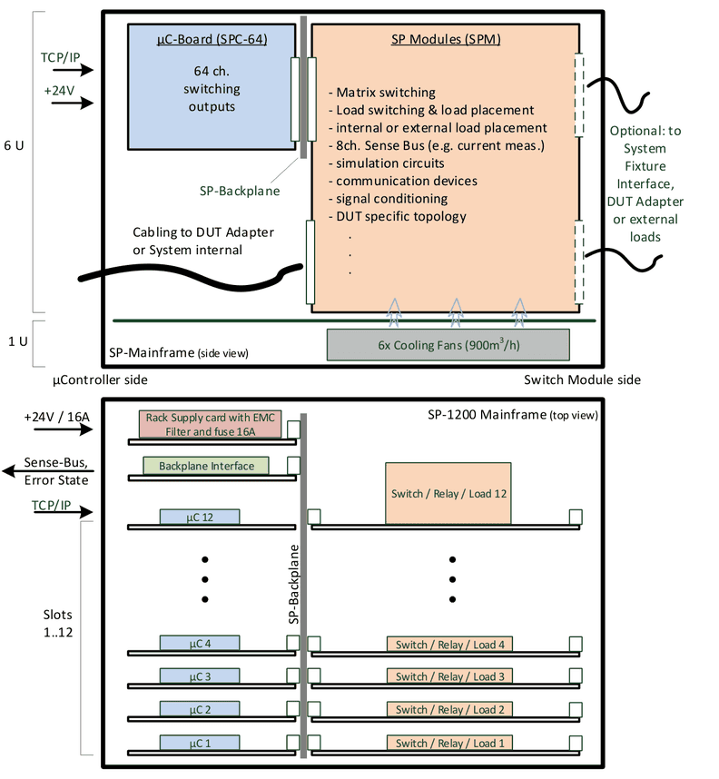


2.4Delivery Content of SP-1200
The SP-1200 basic mainframe includes following components:
- 19‘‘-Rack 7HU, 475mm depth, color RAL7035, ON/OFF switch, 6x cooling fans
- 12-slot backplane for µC and Switch Module population
- Backplane Interface card incl. Error State cable side connector
- SPB Supply card incl. cable side supply input connector
- Switching Platform Software for setup and configuration
- Filler panels 6HU and 3HU for unused slots (front and rear side closed)
2.5Certification & Compliance
| Item | Value |
|---|---|
| Certification of conformity | CE mark by IRS |
| RoHS Compliance | EU RoHS directive 2011/65/EU; Directive (EU) 2015/863 Annex II |
2.6Used Abbreviations
| Abbreviation | Meaning | Description |
|---|---|---|
| SP | Switching Platform | as general term for all Switching Platform products |
| SPC | Switching Platform Controller | 3HU µC card that controls a Switching Platform Module |
| SPM | Switching Platform Module | 6HU pcb with relays and other circuits controlled by a SPC |
| SPW | Switching Platform Wiring | standardized cable to connect a SPM to system interface |
| HU | Height Unit = 44,45 mm | |
| HP | Horizontal Pitch = 5,04 mm | |
| DUT | Device Under Test | same as UUT (unit under test) |
2.7Electrical
| Item | Value | Remarks |
|---|---|---|
| Supply Voltage | 24 Vdc | |
| Supply Current | max. 16 A | Fused via rack supply card |
| Power Consumption | typ. 50..200 W | depending on modules and switching states |
| Power Consumption | max. 400 W | internal power for all µC, modules and fans |
| PE Connection | Required | to test systems cabinet |
2.8Mechanical
| Item | Value | Remarks |
|---|---|---|
| Width | 19‘‘ | app. 483 mm |
| Height | 7 HU | app. 312 mm |
| Depth | 475 mm | rack depth |
| Weight | app. 10,3 kg | no cabling, slot cover panels |
2.9Environment
| Item | Value | Remarks |
|---|---|---|
| Operating Temperature Range | 0..55 °C; 32..131 °F | |
| Operating Humidity Range | 10-80 % | non condensing |
2.10Mainframe Cooling
6 fans in the bottom of the mainframe (1HU) provide an internal air stream of app. 900m³ per hour. They will be activated (switched ON):
- By Backplane Interface card if the mainframe temperature sensor (located in top middle of mainframe) exceeds 40°C
- By any µController (SPC) that detects a temperature of >40°C on its ADC (on modules or external).
They will be de-activated (switched OFF):
- If no µControllers (SPC) and Backplane Interfaces temperature sensor is measuring >35°C
There are 5°C temperature difference to avoid a fast switching ON/OFF situation for the fans. If e.g. 5 µControllers are requesting the “Fan ON State”, then they will be switched to OFF if none of them is requesting “Fans ON” any more.
In case cooling is not sufficient and temperature still raises, any temperature sensor exceeding the value of +80°C leads to complete mainframes error state set to “1”.
2.11Supply & Integration
The SP-1200 mainframe provides a green quick lock 3 pin supply connector for 24Vdc, GND and PE of test systems cabinet on the rack supply slot panel.
Mechanical integration in 19’’-Cabinet via standard L-profile rails. Alternative C-profile rail integration is possible.
The schematic shows an example of basic mechanical and electrical integration of two SP-1200 mainframes in one 19’’-Cabinet of a typical functional test system.
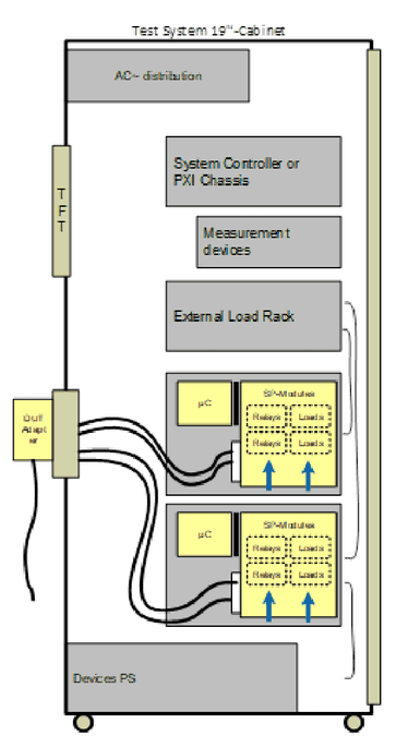
2.12Basic Topology & Design
List of basic IRS Switching Platform design and topology issues:
- Modular concept: switch module side (6HU) for switching execution and load placement. µC side (3HU) of mainframe for communication and switching control.
- The SP Modules basically focus on switching execution and do not contain any control components. Switching control is provided exclusively by separate µController card.
- Each slot with a populated 6HU Switch Module (SPM) requires a 3HU µController card (SPC) connected to the µController side of the slot.
- All modules support 8 channel sense bus access. This allows e.g. 4 current measurements parallel on different load channels.
- Communication to test system controller via TCP/IP protocol, cable connected to one of the µControllers (SPC) in the mainframe.
- Firmware 100% supports multithreading down to module level. Means each module can be controlled by different thread.
- Most modules provide internal diagnostic circuits and features.
2.13Features & Functions
| Feature | Description |
|---|---|
| Module Capacity | Up to 12 SP-Modules (SPM) with standard width 6HP (app. 30mm) can be populated in one mainframe |
| Communication | Via TCP/IP connection, e.g. 192.168.111.240; cable connected to one of the µControllers (no matter which one); cascading of max. 15 mainframes on one TCP/IP port |
| Current Range | Switch Modules classification (max. current): 2A, 10A, 30A, 70A |
| Voltage Range | typ. 48-60Vdc (see module specification); HV Switching matrix module up to 1.000Vdc (1kV) |
| Load Cooling | 6 cooling fans on bottom of rack, air stream app. 900m³ per hour; activation via API command and on module request (temp.-sensors) |
| Digital I/O (per SPC) | 2 bit digital IN, 2 bit dig. OUT per µController card; max. 2mA TTL 3.3V read/set via SW command |
| Error State Contact | Form A relay contact on backplane interface card for internal error state. Contact is closed when no internal error is detected and opens in case of error. Error reasons are: SW freeze (firmware inside SP-1200); Over-Current detected on any high current load channel; Over-Temperature in mainframe or on any high current load channel |
| Current Monitoring | High current modules (>30A) provide internal current monitoring incl. channel switching OFF function: Load channel will be switched OFF by firmware, if current exceeds limit |
| Temperature Monitoring | High current modules (>30A) provide internal temperature monitoring incl. channel switching OFF function: Load channel will be switched OFF by firmware, if current exceeds limit |
| Analog Sense Bus | SP backplane provides 4 ch. dual wire analog sense bus; via 4x SMB connectors on backplane interface; connecting e.g. a DMM allows measuring the voltage drop of an integrated shunt or output voltage of current transducer on the load channels. Basically 4 currents could be measured in parallel. Note: Not all SP-Modules and load channels support current measurement; Load channels may be switched to dedicated sense busses, see module specification |
SP-Editor SW: The topology and population of IRS Switching Platform products can be configured with a SW tool, the Switching Platform Editor:
- SP project definition and handling
- Mainframes, modules and µC configuration
- Auto-Setup function and configuration report file
- Module dependent parameters (e.g. relay bouncing time)
- Alias names for channels (easy understandable switching)
- Current and temperature limits (high current cards 30A, 70A)
- Access levels Operator, Developer, Administrator password protected
- Firmware and database update
- Debug windows for manual control
- Integrated command request builder and documentation
- …
2.14Backplane Interface
2.14.1Connectivity & Status
Backplane interface provides access to SP-1200 mainframe’s analog sense bus (8ch.) and the Error State output. The card shows mainframes status conditions via the LEDs Power, Error and Ethernet and allows an IP reset.
The interface also works as a switch for internal TCP/IP distribution to each slot (each slot has own IP address).
For each SP-1200 mainframe the IP Address has to be set in this interface card.
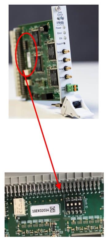
2.14.2IP Address Setting
Default value of each SP-1200 mainframes IP Address is: 192.168.111.0
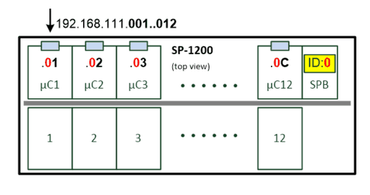
With a 4pin DIP switch on the backplane interface card (right side next to the SNr. Label) the Rack-ID can be set from “0x0” to ”0xE”. This also sets the high nibble of last part of the IP Address. The low nibble is defined by hardware from “0x1” to “0xC” for each slot.
This defines following default IP Address structure in the SP-1200:
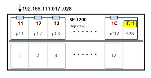
Setting the Rack-ID switch from “0” to “1” changes the mainframes IP Address range:
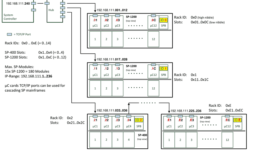
Example topology with multiple SP Mainframes:
2.14.3Controller IP Setting
The IP Address range for a Switching Platform topology with 15 SP-1200 mainframes is from 192.168.111.1 up to 192.168.111.236. To avoid collisions, a good IP Address for a controller (PC, Laptop, PXI-Controller, ..) would be e.g.: 192.168.111.240.
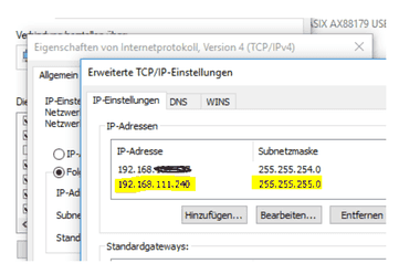
2.14.4Change Mainframes IP Address
The mainframes IP address can be changed via the SP Software: Rack – Change IP Address. This requires developer login.
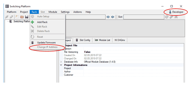
2.15Rack Supply Card
The 24Vdc supply voltage for the SP-1200 mainframe is applied via the green 3pin Quick Lock connector. For removal both locking springs need to be pressed to unplug the connector.
+24Vdc, GND and test systems PE need to be connected, the cable side connector is included in delivery. The input is fused with 16A.
All wires need minimum width AWG14 or equivalent 2,5mm².
| Signal | Pin | Position |
|---|---|---|
| +24Vdc | 1 | Top pin |
| GND (24V) | 2 | Middle pin |
| PE | 3 | Bottom pin |

2.16Switching Platform SW
With each SP-1200 mainframe the Switching Platform SW is delivered. Installation of this SW provides .NET API functions, wrapper functions for C, the IRS module database and a SP-Editor.
The Switching Platform Editor is a tool for comfortable configuration of the complete Switching Platform topology in the test system. All mainframes and their IP Addresses including their module population can be defined and stored in a project file with this tool.
The project file needs to be loaded in the test sequence beginning to allow the control of all switching paths and other functions.
Following files are provided: .exe files for installation on 32-bit or 64-bit systems, Firmware for SP µControllers (.ebin file) and the SP Module Database (.spm file) that includes all available SP-Modules and their parameters.
The .NET Framework 4.7 need to be installed on the controller to run the SP SW.
2.17Sense Bus Measurement
The internal Sense Busses 1..4 can be connected via 4x SMB sockets to external measurement devices (e.g. via some measurement matrix). Shunts or current transducers on the load channels can be connected to the Sense Busses 1..4 by closing the sense relays on the module.
This topology allows in general 4 parallel measurements inside the SP mainframe. Not all load channels can be switched to every sense bus, possible connections are defined in the modules datasheet.
The firmware verifies that only one sense relay is connected to a sense bus at the same time. If already another channel is connected, the API function responds an error.
Example with 70A high current module:
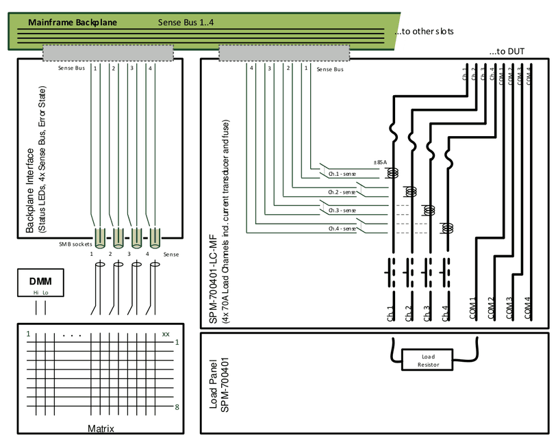
2.18Error State
The Error State output reflects mainframe internal errors to devices outside of the mainframe in order to react on critical conditions. Via ADC inputs each µC card (SPC) is monitoring the current and temperature sensors on the module in the corresponding backplane slot. In case of limit exceeding, the SPC sets the Error State to “1” for the whole mainframe.
Main purpose is to connect the Error State output to the Interlock input of a power supply, so in case of an error the PS will switch off and remove potentially dangerous voltage and current from test system and DUT.
The error state can also be connected to e.g. dig. I/O devices read by test systems controller to react inside test sequence on error state condition.
The Error State is set to “1” (means relay contact opens):
- Over current condition: Any load channels current monitoring detected a current exceeding the set limits (set in SP-Editor by default or custom specific).
- Over temperature condition: Any load channels or modules temperature monitoring detected a temperature exceeding the set limits (set in SP-Editor by default or custom specific). Some modules also provide external temperature sensors. This sensors can be used also outside of the SP mainframe e.g. in the test systems cabinet. Independent from SP-Modules the mainframe has a temperature sensor located on top middle of the rack. Via the backplane interface this sensor will activate the fans when >40°C and also raise overtemperature condition when >80°C.
- Firmware freeze: Internal running firmware is re-setting the error state permanently to „0“. If this function is not executed, the error state will switch to „1“ by HW circuits.
In case of Error State is “1”, each API command sent to mainframe will receive a corresponding error message and the command will not be executed.
The Error State can be reset by API function.
Functional schematic with 70A high current module:
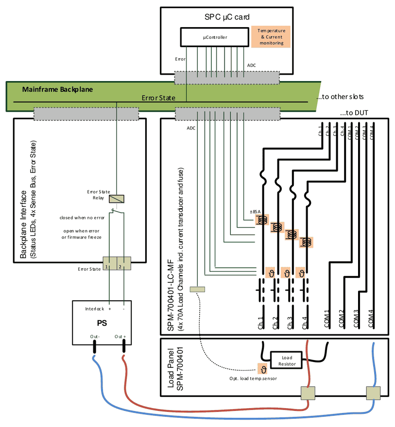
2.19Populating & Removal of Modules
- Disconnect 24V supply or switch off the mainframe before plugging/removing cards.
- To remove modules, first unscrew the panels on top and bottom of SPM holder
- Then press grey locks at the same time and
- Move the holders to unplug the cards from backplane and modules cabling connectors
- Pull the module carefully out of the slot
- Some modules have components mounted on pcb bottom side (left side). To avoid collision with panels of neighbor modules and damage the module the movement must be done very sensitive.
For plugging of modules perform the reverse procedure from 5. to 2. with unpowered or switched OFF mainframe.
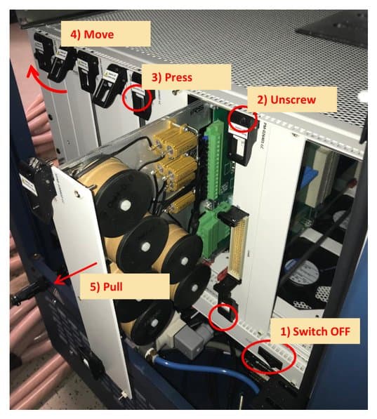
2.20List of Available Modules
| Module ID | Module Type | Description |
|---|---|---|
| SPM-300801-FS | Fault Simulation 8 Ch. 30A | Connect DUT pins to short busses |
| SPM-014002-HV | High Voltage Matrix 1kV | 40 ch. 1A configurable High Voltage Matrix |
| SPM-021604-MX | Matrix 16x4 ch. 2A | 16 rows (2A) to 4 columns (10A), selftest: relay readback |
| SPM-023206-MX | Matrix 32x6 ch. 2A | 32 rows (2A) to 2 columns (10A), selftest: relay readback |
| SPM-026401-LC | Loadcard 64 ch. 2A | 64x form A contacts 2A, selftest: relay readback, load breakout pcb |
| SPM-100802-LC | Loadcard 8x2 ch. 10A | 8x2 form A contacts 10A, current measurement by shunt or current transducer, mounting panel or load breakout pcb |
| SPM-300602-LC | Loadcard 6x2 ch. 30A | 6x2 form A contacts 30A, selftest: test current loop, mounting panel or load breakout pcb |
| SPM-700401-LC | Loadcard 4 ch. 70A | 4x form A contacts 70A, selftest: test current loop, mounting panel or load breakout pcb |
| SPM-700401-LC-MF | Loadcard 4 ch. 70A | 4x MOS-FET switches 70A, selftest: test current loop, mounting panel or load breakout pcb |
| SPM-SYS-001 | System Module | System Module; 8x diff. signal switching, auxiliary DC power supply, monitoring (5V, 12V, 24V), 16x Dig. IN, 12x Dig. OUT |
| SPM-1000201-ME-CMM | Measurement Module current µA – 100A | 2x CMM-III autoranging current measurement devices, incl. factory- or DAkkS-calibration, selftest: current loop |
2.21Sparepart List
| Manufacturer / Supplier | Part Nr. | IRS Part Nr. | Component Description |
|---|---|---|---|
| IRS GmbH | SP-1200 | 121466 | Mainframe Switching Platform 12 slot v2 |
| IRS GmbH | SPB Switch | 119151 | SP Backplane Interface card |
| IRS GmbH | SPB Supply | 121461 | SP Supply card v1.1 |
| IRS GmbH | SPC-64 | 120701 | SP µController card v2.2 |
| Würth Elektronik | 691304530003 | 121013 | Supply connector 3pin |
| Phoenix Contact | FMC 1,5/ 2-ST-3,81 | 109439 | Error State Output connector 2pin |
2.22Product Support
- IRS Homepage: www.irs.systems
- Email Contact: info@irs.systems
Datasheet SPM-021604-MX
SPM-021604-MX – IRS product 119357 SPM-021604-MX-E, 4x16 Matrix, 2A, breakout pcb; hardware version 1.1.
3.1General Description
The SPM-021604-MX is a low current 6HU switching module for use inside IRS Switching Platform mainframes. The module provides a 4 columns x 16 rows matrix topology for max. 2A per row and 10A current per column.
Each of the 16 rows (= channels) is fused with a 2A fast fuse on DUT input side and additional on the breakout side.
Internal diagnostic is possible via crosspoint switching state readback also available as an API function. More matrix cards can be combined (e.g. via the breakout connector) to increase the number of rows/channels.
Typical tasks are flexible load, measurement and supply switching to DUT pins up to 2A current. The module is available with a metal panel with a closed front panel and a breakout extension pcb for wiring to external devices or other matrix cards.
3.2Safety Instructions
- Only for use in IRS Switching Platform mainframes (e.g. SP-1200) and within the specified electrical limits.
- Use only inside suitable 19‘‘-Cabinets and not for applications to humans or animals.
- Use this SP module only with the SPC-64 µController card (PN: 120701) and with the SP-Editor SW and its API commands for configuration and control
- Hot switching is NOT recommended on any circuit of the module. This will reduce the lifetime and maximum switching cycles of the relays and possibly destroy the relays on the module.
- The module is designed for resistive loads, user has to care about protection circuitry when using inductive or capacitive loads
- Outputs need sufficient isolation and protection against contact.
3.3Schematic Overview & Pictures


3.4Scope of Delivery
SPM-021604-MX-E:
- Switching pcb completely assembled with breakout pcb
- Frontpanel with breakout connectors and all required cable side connectors
3.5Certification & Compliance
| Item | Value |
|---|---|
| Certification of conformity | CE mark by IRS |
| RoHS Compliance | EU RoHS directive 2011/65/EU; Directive (EU) 2015/863 Annex II |
3.6Used Abbreviations
| Abbreviation | Meaning | Description |
|---|---|---|
| SP | Switching Platform | a general term for all Switching Platform products |
| SPB | Backplane Interface | Interface card for SP Mainframe (e.g. SP-1200) |
| SPC | Switching Platform Controller | 3HU µC card that controls a Switching Platform Module |
| SPM | Switching Platform Module | 6HU pcb with relays and other circuits controlled by a SPC-64 µController card |
| SPW | Switching Platform Wiring | standardized cable from a SPM to system interface |
| DUT | Device Under Test | same as UUT (unit under test) |
| CT | Current Transducer | inductive current measurement device |
| HU | Height Unit = 44,45 mm | |
| HP | Horizontal Pitch = 5,04 mm |
3.7Electrical
3.7.1Matrix Channel Specification
| Item | Value | Remarks |
|---|---|---|
| Rated Voltage | 60 Vdc | stationary |
| Rated Current / Channel | 2 A (row); 10 A (col) | stationary |
| Switching Power (resistive load) | 2 A at <30 V; 1 A at <60 V | -> hot switching reduces lifetime ! |
| Fuse / Channel | 2 A | fast fuse, per row (DUT side and breakout side) |
This values include the complete load channel incl. all components (connectors, pcb routes, fuse, current transducer, ..).
3.7.2Relay Specification
The current and voltage ratings of the relay are shown for information only. The “Load Channel Specification“ table shown above has to be used when creating a circuit using this module. The ratings in the “Load Channel Specification“ table are lower than the ratings for the relay by itself.
| Item | Value | Remarks |
|---|---|---|
| Max. Current | 2 A | stationary |
| Max. Voltage | 220 V | DC stationary |
| Switching Power (resistive load) | 2 A at <30 V; 1 A at <60 V; 0,3 A at 220Vdc | hot switching reduces lifetime! |
| Operating Time | max. 4 ms | excl. bouncing time |
| Mechanical Life | > 1x10^8 cycles | without el. load |
3.8Mechanical
| Item | Value | Remarks |
|---|---|---|
| Width | 6 HP | = 30,24 mm; standard width (1 slot) |
| Height | 6 HU | = 266,7 mm |
| Depth | ~ 365 mm | |
| Weight | ~ 0,640 kg |
3.9Environment
| Item | Value | Remarks |
|---|---|---|
| Operating Temperature Range | 0..55 °C; 32..131 °F | |
| Operating Humidity Range | 10-80 % | non condensing |
3.10Topology & Functions
| Item | Value | Description |
|---|---|---|
| Nr. of channels | 16 x 4 | Matrix topology with 64 crosspoints: 16 rows connectable to 4 columns |
| Loads / Channel | 1 | signal per channel |
| Fused Channels | 16 | 16 channels, fast fuse 2A DUT and load side |
| Internal Diagnostic | yes, readback | 2nd relay contact allows readback of switching state via API command and internal diagnostic to verify contact functionality; incl. report generation |
| Load Options | -E | External breakout pcb |
| User ID | Yes | Via SP-Editor a user defined identification string will be stored in modules EEPROM (e.g. Load ID, ..) |
| Memory Objects | Yes | Via SP-Editor memory objects can be defined and stored in modules EEPROM (e.g. calibration data, additional module information, ..); max. 6kB |
| Load Relay Cycle Counter | yes | switching cycle of each relay is counted and stored in modules EEPROM; status can be read via SW command |
3.11Sense Bus Measurement
No current measurement and Sense Bus available on this module.
3.12Component Location
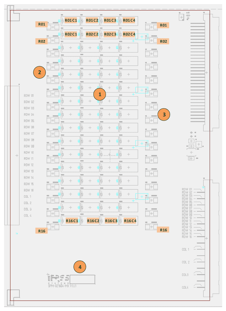
| No. | Component |
|---|---|
| 1 | Crosspoint relays for row 1 - 16 & column 1 – 4 |
| 2 | Fuse breakout side 2A for row 1 - 16 |
| 3 | Fuse DUT side 2A for row 1 - 16 |
| 4 | Serial number and quality check labels |
3.13Connectivity
3.13.1DUT Side Connector Pinout
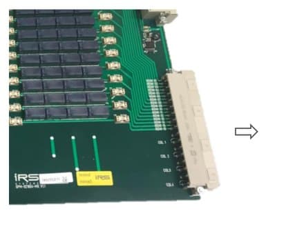
SPM-021604-MX connector X2:
| Pin | z | d |
|---|---|---|
| 2 | Row 1 | Row 2 |
| 4 | Row 3 | Row 4 |
| 6 | Row 5 | Row 6 |
| 8 | Row 7 | Row 8 |
| 10 | Row 9 | Row 10 |
| 12 | Row 11 | Row 12 |
| 14 | Row 13 | Row 14 |
| 16 | Row 15 | Row 16 |
| 18 | ||
| 20 | Col 1 | Col 1 |
| 22 | ||
| 24 | Col 2 | Col 2 |
| 26 | ||
| 28 | Col 3 | Col 3 |
| 30 | ||
| 32 | Col 4 | Col 4 |
X2 connector layout for cable to DUT/Adapter
For cabling to system’s receiver interface or to DUT Adapter following data needs to be considered:
| Item | Value | Remarks |
|---|---|---|
| Max. current | 6 A | per connector pin (crosspoints limited to 2A!) |
| Used pins | 1 | pins used per row |
| Used pins | 2 | pins used per column |
| Wire cross sections | AWG 20 / 0,5 mm² | per row wire |
| Wire cross sections | AWG 16 / 1,5 mm² | per column wire |
3.13.2Breakout Connector Pinout
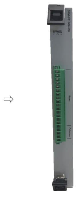
| Breakout pin | Signal |
|---|---|
| 1 | Row 1 |
| 2 | Row 2 |
| 3 | Row 3 |
| 4 | Row 4 |
| 5 | Row 5 |
| 6 | Row 6 |
| 7 | Row 7 |
| 8 | Row 8 |
| 9 | Row 9 |
| 10 | Row 10 |
| 11 | Row 11 |
| 12 | Row 12 |
| 13 | Row 13 |
| 14 | Row 14 |
| 15 | Row 15 |
| 16 | Row 16 |
| 17 | Col 1 |
| 18 | Col 2 |
| 19 | Col 3 |
| 20 | Col 4 |
The breakout connector can easily be used as parallel matrix crosspoints access e.g. for debugging purposes.
For cabling to breakout interface following data needs to be considered:
| Item | Value | Remarks |
|---|---|---|
| Max. current | 12 A | per connector pin (crosspoints limited to 2A!) |
| Used pins | 1 | pin used per row and per column |
| Wire cross sections | AWG 20 / 0,5 mm² | per row wire |
| Wire cross sections | AWG 16 / 1,5 mm² | per column wire |
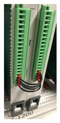
3.13.3Linked Matrix Columns
Multiple SPM-021604-MX Matrix modules can be used either with separated columns, or the columns can be linked together to achieve more crosspoints (e.g. 4x 32 or 4x 48, ..).
The connection of the columns between the modules can be done on X2 connector side as an SP-1200 internal wiring. Alternatively this connection can be done on the breakout connector as shown on the picture.
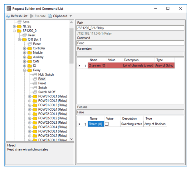
3.14Relay State Readback
The second contact of cross point relay is card internally used for switching state indication. Via API command the state of cross point relay(s) can be read back.
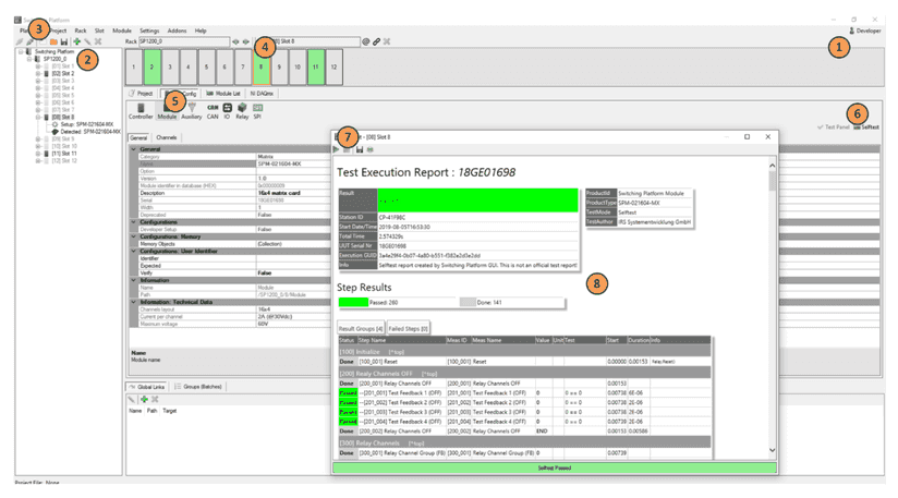
3.15Diagnostics & Selftest
The SPM-021604-MX provides internal selftest sequence that switches each single crosspoint and verifies the switching state. After performing the selftest sequence a report is generated that can be stored by user for documentation purposes.
Start Switching Platform Editor SW – (1) login as developer – (2) load project configuration file or add new mainframe with autodetect – (3) connect SP mainframe – (4) select slot with SPM-021604-MX card – (5) select “Slot Config” Tab and “Module” – (6) select “Selftest” – (7) run selftest by pressing blue arrow – (8) review/save selftest report
3.16Sparepart List
| Manufacturer / Supplier | Part Nr. | IRS Part Nr. | Component Description |
|---|---|---|---|
| Panasonic | TX2-24V | 112828 | Relay 2A, 2 form C, 24Vdc |
| Littelfuse | 0154002.DR | 119358 | Fuse 2A, SMD |
| Phoenix Contact | MSTB 2,5/20-STF-5,08 | 118491 | Breakout connector cable side, 20 pin |
| Harting | DIN41612 VG-48F | 101422 | X2 cable side female connector |
3.17Product Support
- IRS Homepage: www.irs.systems
- Email Contact: info@irs.systems
Datasheet SPM-026401-LC
SPM-026401-LC – IRS product 119786 SPM-026401-LC-E, 64 Single channels, 2A, load breakout pcb; hardware version 1.00.
4.1General Description
The SPM-026401-LC is a low current 6HU switching module for use inside IRS Switching Platform mainframes. The module topology provides 64 single load switching channels for max. 2A continuous current.
Each of the 64 channels can be used in three basic configurations:
- Form A, Channel to Common normally open contact
- Load switching between Channel to Common
- Load switching between Channel to Power Busses 1..4 (e.g. GND, Vcc, ..)
This channel configurations are done on the breakout & load mounting extension pcb.
Typical tasks are flexible load, measurement and supply switching to DUT pins up to 2A current. The module provides a load mounting and breakout pcb including a connector for wiring to external devices or loads.
4.2Safety Instructions
- Only for use in IRS Switching Platform mainframes (e.g. SP-1200) and within the specified electrical limits.
- Use only inside suitable 19‘‘-Cabinets and not for applications to humans or animals.
- Use this SP module only with the SPC-64 µController card (PN: 120701) and with the SP-Editor SW and its API commands for configuration and control
- Hot switching is NOT recommended on any circuit of the module. This will reduce the lifetime and maximum switching cycles of the relays and possibly destroy the relays on the module.
- The module is designed for resistive loads, user has to care about protection circuitry when using inductive or capacitive loads
- Outputs need sufficient isolation and protection against contact.
4.3Schematic Overview & Pictures


4.4Scope of Delivery
SPM-026401-LC-E:
- Switching pcb completely assembled with breakout & load mounting pcb
- Frontpanel with breakout connectors and all required cable side connectors
4.5Certification & Compliance
| Item | Value |
|---|---|
| Certification of conformity | CE mark by IRS |
| RoHS Compliance | EU RoHS directive 2011/65/EU; Directive (EU) 2015/863 Annex II |
4.6Used Abbreviations
| Abbreviation | Meaning | Description |
|---|---|---|
| SP | Switching Platform | a general term for all Switching Platform products |
| SPB | Backplane Interface | Interface card for SP Mainframe (e.g. SP-1200) |
| SPC | Switching Platform Controller | 3HU µC card that controls a Switching Platform Module |
| SPM | Switching Platform Module | 6HU pcb with relays and other circuits controlled by a SPC-64 µController card |
| SPW | Switching Platform Wiring | standardized cable from a SPM to system interface |
| DUT | Device Under Test | same as UUT (unit under test) |
| CT | Current Transducer | inductive current measurement device |
| HU | Height Unit = 44,45 mm | |
| HP | Horizontal Pitch = 5,04 mm |
4.7Electrical
4.7.1Load Channel Specification
| Item | Value | Remarks |
|---|---|---|
| Rated Voltage | 60 Vdc | stationary |
| Rated Current / Channel | 2 A | stationary |
| Rated Current / Power Bus | 10 A | stationary |
| Switching Power (resistive load) | 2 A at <30 V; 1 A at <60 V | -> hot switching reduces lifetime ! |
| Fuse / Channel | - no fuse - | channels are not fused |
| Channel Resistance | 700–900 mOhm | typical value between X2 Ch.x and COM Ch. x incl. breakout pcb |
This values include the complete load channel incl. all components (connectors, pcb routes, fuse, current transducer, ..).
4.7.2Relay Specification
The current and voltage ratings of the relay are shown for information only. The “Load Channel Specification“ table shown above has to be used when creating a circuit using this module. The ratings in the “Load Channel Specification“ table are lower than the ratings for the relay by itself.
| Item | Value | Remarks |
|---|---|---|
| Max. Current | 2 A | stationary |
| Max. Voltage | 220 V | DC stationary |
| Switching Power (resistive load) | 2 A at <30 V; 1 A at <60 V; 0,3 A at 220Vdc | hot switching reduces lifetime! |
| Operating Time | max. 4 ms | excl. bouncing time |
| Mechanical Life | > 1x10^8 cycles | without el. load |
4.8Mechanical
| Item | Value | Remarks |
|---|---|---|
| Width | 6 HP | = 30,24 mm; standard width (1 slot) |
| Height | 6 HU | = 266,7 mm |
| Depth | ~ 365 mm | |
| Weight | ~0,825 kg | Incl. cable side breakout connector |
4.9Environment
| Item | Value | Remarks |
|---|---|---|
| Operating Temperature Range | 0..55 °C; 32..131 °F | |
| Operating Humidity Range | 10-80 % | non condensing |
4.10Topology & Functions
| Item | Value | Description |
|---|---|---|
| Nr. of channels | 64 | Single channels, form A contact (com – no) |
| Loads / Channel | 1 | Load per channel |
| Fused Channels | - no fuse - | Channels not fused |
| Internal Diagnostic | yes, readback | 2nd relay contact allows readback of switching state via API command and internal diagnostic to verify contact functionality; incl. report generation |
| Load Options | -E | External breakout & load placement pcb |
| User ID | Yes | Via SP-Editor a user defined identification string will be stored in modules EEPROM (e.g. Load ID, ..) |
| Memory Objects | Yes | Via SP-Editor memory objects can be defined and stored in modules EEPROM (e.g. calibration data, additional module information, ..); max. 6kB |
| Load Relay Cycle Counter | yes | switching cycle of each relay is counted and stored in modules EEPROM; status can be read via SW command |
| Load Placement | On pcb | Resistors up to 2W can be soldered on the breakout pcb |
The breakout pcb provides already 64 blue jumper connectors for the form A configuration (using channels as a form A relay COM-NO). By removing this short bridge, the load channel is open and requires a load resistor soldered on the pcb.
4.11Sense Bus Measurement
No current measurement and Sense Bus available on this module.
4.12Component Location
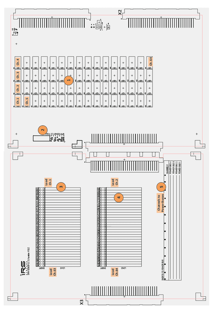
| No. | Component |
|---|---|
| 1 | Channel relays 1 - 64 |
| 2 | Serial number and quality check labels |
| 3 | Short/load area for channels 1 – 63 (odd numbers) |
| 4 | Short/load area for channels 2 – 64 (even numbers) |
| 5 | Short bridge area for channels short to power busses connections |
4.13Connectivity
4.13.1DUT Side Connector Pinout
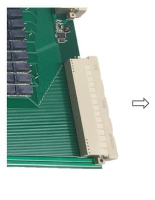
SPM-026401-LC connector X2:
| Pin row | a | b | c | d | e |
|---|---|---|---|---|---|
| 1 | PB1 | Ch. 1 | Ch. 2 | Ch. 3 | Ch. 4 |
| 2 | PB1 | Ch. 5 | Ch. 6 | Ch. 7 | Ch. 8 |
| 3 | PB1 | Ch. 9 | Ch. 10 | Ch. 11 | Ch. 12 |
| 4 | PB1 | Ch. 13 | Ch. 14 | Ch. 15 | Ch. 16 |
| 5 | PB1 | Ch. 17 | Ch. 18 | Ch. 19 | Ch. 20 |
| 6 | PB1 | Ch. 21 | Ch. 22 | Ch. 23 | Ch. 24 |
| 7 | PB1 | Ch. 25 | Ch. 26 | Ch. 27 | Ch. 28 |
| 8 | PB1 | Ch. 29 | Ch. 30 | Ch. 31 | Ch. 32 |
| 9 | PB2 | Ch. 33 | Ch. 34 | Ch. 35 | Ch. 36 |
| 10 | PB2 | Ch. 37 | Ch. 38 | Ch. 39 | Ch. 40 |
| 11 | PB2 | Ch. 41 | Ch. 42 | Ch. 43 | Ch. 44 |
| 12 | PB2 | Ch. 45 | Ch. 46 | Ch. 47 | Ch. 48 |
| 13 | PB2 | Ch. 49 | Ch. 50 | Ch. 51 | Ch. 52 |
| 14 | PB2 | Ch. 53 | Ch. 54 | Ch. 55 | Ch. 56 |
| 15 | PB2 | Ch. 57 | Ch. 58 | Ch. 59 | Ch. 60 |
| 16 | PB2 | Ch. 61 | Ch. 62 | Ch. 63 | Ch. 64 |
| 17 | PB3 | COM Ch. 1 | COM Ch. 2 | COM Ch. 3 | COM Ch. 4 |
| 18 | PB3 | COM Ch. 5 | COM Ch. 6 | COM Ch. 7 | COM Ch. 8 |
| 19 | PB3 | COM Ch. 9 | COM Ch. 10 | COM Ch. 11 | COM Ch. 12 |
| 20 | PB3 | COM Ch. 13 | COM Ch. 14 | COM Ch. 15 | COM Ch. 16 |
| 21 | PB3 | COM Ch. 17 | COM Ch. 18 | COM Ch. 19 | COM Ch. 20 |
| 22 | PB3 | COM Ch. 21 | COM Ch. 22 | COM Ch. 23 | COM Ch. 24 |
| 23 | PB3 | COM Ch. 25 | COM Ch. 26 | COM Ch. 27 | COM Ch. 28 |
| 24 | PB3 | COM Ch. 29 | COM Ch. 30 | COM Ch. 31 | COM Ch. 32 |
| 25 | PB4 | COM Ch. 33 | COM Ch. 34 | COM Ch. 35 | COM Ch. 36 |
| 26 | PB4 | COM Ch. 37 | COM Ch. 38 | COM Ch. 39 | COM Ch. 40 |
| 27 | PB4 | COM Ch. 41 | COM Ch. 42 | COM Ch. 43 | COM Ch. 44 |
| 28 | PB4 | COM Ch. 45 | COM Ch. 46 | COM Ch. 47 | COM Ch. 48 |
| 29 | PB4 | COM Ch. 49 | COM Ch. 50 | COM Ch. 51 | COM Ch. 52 |
| 30 | PB4 | COM Ch. 53 | COM Ch. 54 | COM Ch. 55 | COM Ch. 56 |
| 31 | PB4 | COM Ch. 57 | COM Ch. 58 | COM Ch. 59 | COM Ch. 60 |
| 32 | PB4 | COM Ch. 61 | COM Ch. 62 | COM Ch. 63 | COM Ch. 64 |
X2 connector layout for cable to DUT/Adapter
For cabling to system’s receiver interface or to DUT Adapter following data needs to be considered:
| Item | Value | Remarks |
|---|---|---|
| Max. current | 2 A | per connector pin |
| Used pins | 1 | pin used per channel |
| Used pins | 8 | pins used per Power Bus |
| Wire cross sections | AWG 20 / 0,35 mm² | per channel wire |
| Wire cross sections | AWG 16 / 1,5 mm² | per power bus wire |
4.13.2Breakout Connector Pinout
Cable side breakout connector (ERNI) incl. 160 pins (ERNI 234063) delivered with the SP-Module:
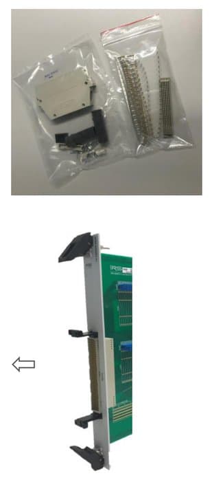
SPM-026401-LC connector X3 (Load Breakout):
| Pin row | a | b | c | d | e |
|---|---|---|---|---|---|
| 1 | PB1 | COM Ch. 61 | COM Ch. 62 | COM Ch. 63 | COM Ch. 64 |
| 2 | PB1 | COM Ch. 57 | COM Ch. 58 | COM Ch. 59 | COM Ch. 60 |
| 3 | PB1 | COM Ch. 53 | COM Ch. 54 | COM Ch. 55 | COM Ch. 56 |
| 4 | PB1 | COM Ch. 49 | COM Ch. 50 | COM Ch. 51 | COM Ch. 52 |
| 5 | PB1 | COM Ch. 45 | COM Ch. 46 | COM Ch. 47 | COM Ch. 48 |
| 6 | PB1 | COM Ch. 41 | COM Ch. 42 | COM Ch. 43 | COM Ch. 44 |
| 7 | PB1 | COM Ch. 37 | COM Ch. 38 | COM Ch. 39 | COM Ch. 40 |
| 8 | PB1 | COM Ch. 33 | COM Ch. 34 | COM Ch. 35 | COM Ch. 36 |
| 9 | PB2 | COM Ch. 29 | COM Ch. 30 | COM Ch. 31 | COM Ch. 32 |
| 10 | PB2 | COM Ch. 25 | COM Ch. 26 | COM Ch. 27 | COM Ch. 28 |
| 11 | PB2 | COM Ch. 21 | COM Ch. 22 | COM Ch. 23 | COM Ch. 24 |
| 12 | PB2 | COM Ch. 17 | COM Ch. 18 | COM Ch. 19 | COM Ch. 20 |
| 13 | PB2 | COM Ch. 13 | COM Ch. 14 | COM Ch. 15 | COM Ch. 16 |
| 14 | PB2 | COM Ch. 9 | COM Ch. 10 | COM Ch. 11 | COM Ch. 12 |
| 15 | PB2 | COM Ch. 5 | COM Ch. 6 | COM Ch. 7 | COM Ch. 8 |
| 16 | PB2 | COM Ch. 1 | COM Ch. 2 | COM Ch. 3 | COM Ch. 4 |
| 17 | PB3 | Ch. 61 | Ch. 62 | Ch. 63 | Ch. 64 |
| 18 | PB3 | Ch. 57 | Ch. 58 | Ch. 59 | Ch. 60 |
| 19 | PB3 | Ch. 53 | Ch. 54 | Ch. 55 | Ch. 56 |
| 20 | PB3 | Ch. 49 | Ch. 50 | Ch. 51 | Ch. 52 |
| 21 | PB3 | Ch. 45 | Ch. 46 | Ch. 47 | Ch. 48 |
| 22 | PB3 | Ch. 41 | Ch. 42 | Ch. 43 | Ch. 44 |
| 23 | PB3 | Ch. 37 | Ch. 38 | Ch. 39 | Ch. 40 |
| 24 | PB3 | Ch. 33 | Ch. 34 | Ch. 35 | Ch. 36 |
| 25 | PB4 | Ch. 29 | Ch. 30 | Ch. 31 | Ch. 32 |
| 26 | PB4 | Ch. 25 | Ch. 26 | Ch. 27 | Ch. 28 |
| 27 | PB4 | Ch. 21 | Ch. 22 | Ch. 23 | Ch. 24 |
| 28 | PB4 | Ch. 17 | Ch. 18 | Ch. 19 | Ch. 20 |
| 29 | PB4 | Ch. 13 | Ch. 14 | Ch. 15 | Ch. 16 |
| 30 | PB4 | Ch. 9 | Ch. 10 | Ch. 11 | Ch. 12 |
| 31 | PB4 | Ch. 5 | Ch. 6 | Ch. 7 | Ch. 8 |
| 32 | PB4 | Ch. 1 | Ch. 2 | Ch. 3 | Ch. 4 |
X3 connector layout for cable to external loads
For cabling to breakout interface following data needs to be considered:
| Item | Value | Remarks |
|---|---|---|
| Max. current | 2 A | per connector pin |
| Used pins | 1 | pin used per channel |
| Used pins | 8 | pins used per Power Bus |
| Wire cross sections | AWG 20 / 0,35 mm² | per channel wire |
| Wire cross sections | AWG 16 / 1,5 mm² | per power bus wire |
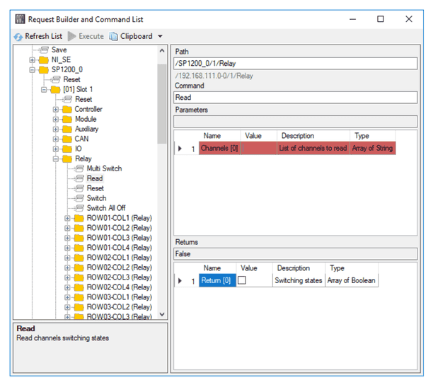
4.14Relay State Readback
The second contact of cross point relay is card internally used for switching state indication. Via API command the state of cross point relay(s) can be read back.
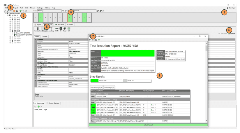
4.15Diagnostics & Selftest
The SPM-026401-LC provides an internal selftest sequence that switches each single load channel relay and verifies the switching state. After performing the selftest sequence a report is generated that can be stored by user for documentation purposes.
Start Switching Platform Editor SW – (1) login as developer – (2) load project configuration file or add new mainframe with autodetect – (3) connect SP mainframe – (4) select slot with SPM-026401-LC card – (5) select “Slot Config” Tab and “Module” – (6) select “Selftest” – (7) run selftest by pressing blue arrow – (8) review/save selftest report
4.16Load Configuration Examples
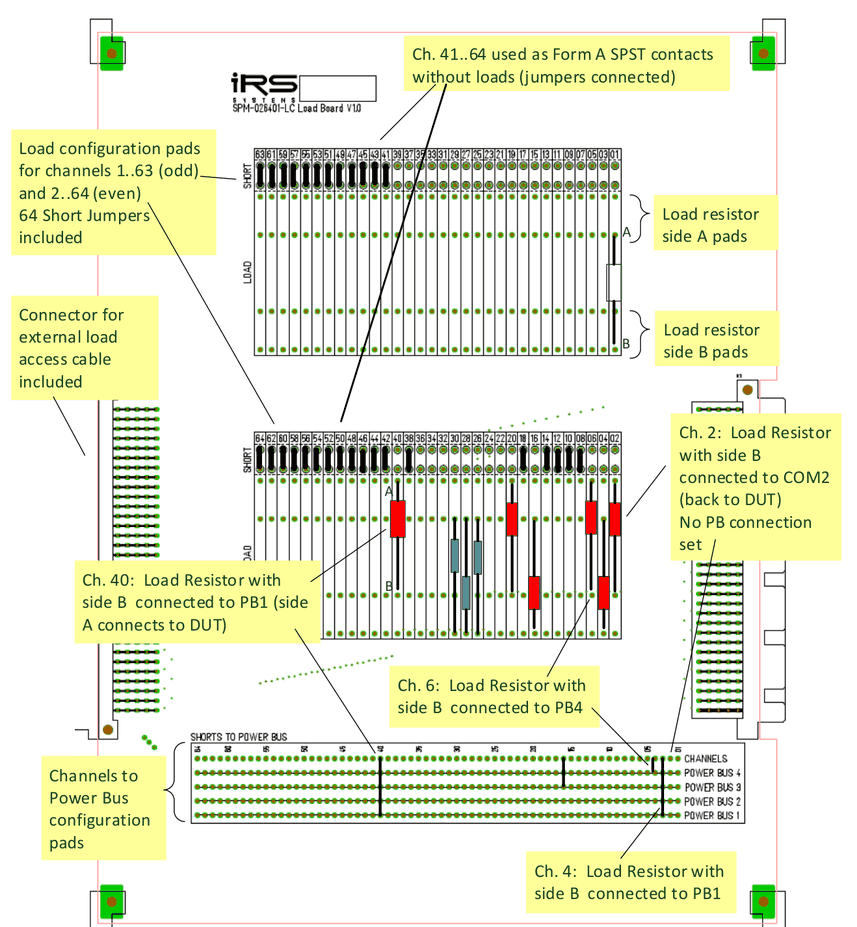
Labels in the picture:
- Load configuration pads for channels 1..63 (odd) and 2..64 (even); 64 Short Jumpers included
- Load resistor side A pads; Load resistor side B pads
- Connector for external load access cable included
- Channels to Power Bus configuration pads
- Ch. 41..64 used as Form A SPST contacts without loads (jumpers connected)
- Ch. 40: Load Resistor with side B connected to PB1 (side A connects to DUT)
- Ch. 2: Load Resistor with side B connected to COM2 (back to DUT), No PB connection set
- Ch. 4: Load Resistor with side B connected to PB1
- Ch. 6: Load Resistor with side B connected to PB4
4.17Sparepart List
| Manufacturer / Supplier | Part Nr. | IRS Part Nr. | Component Description |
|---|---|---|---|
| Panasonic | TX2-24V | 112828 | Relay 2A, 2 form C, 24Vdc |
| ERNI | 024070 | 100205 | X3 cable side: 160 pin module |
| ERNI | 173052 | 103032 | X3 cable side: cable housing KSG173 |
| ERNI | 234063 | 101480 | X3 cable side: Pins (qty. 500) |
| Stäubli | KB1-5,08 BLUE | 112628 | Connecting Bridges |
4.18Product Support
- IRS Homepage: www.irs.systems
- Email Contact: info@irs.systems
Datasheet SPM-100802-LC
SPM-100802-LC – IRS products 119783 SPM-100802-LC-E, 8 Dual channels, 10A, load breakout pcb, and 119912 SPM-100802-LC-P, 8 Dual channels, 10A, load mounting panel; hardware version 1.2.2.
5.1General Description
The SPM-100802-LC is a medium current 6HU switching module for use inside IRS Switching Platform mainframes. The module topology provides 8 dual load switching channels for max. 10A continuous current with fuse and integrated shunt for current measurement in each channel.
Each channel can be configured via jumper to be a dual or a single channel what provides a max. of 16 single channels for 10A load switching purposes.
For precise current measurements an external current measurement device (e.g. DMM) can be connected to the module and via switching be routed in series into the load path. This allows calibrated current measurements directly in the load path.
Typical tasks are load and supply switching to DUT with flexible and precise current measurement requirements. The module is available with a metal panel for load mounting or a breakout extension for wiring to external placed loads.
5.2Safety Instructions
- Only for use in IRS Switching Platform mainframes (e.g. SP-1200) and within the specified electrical limits.
- Use only inside suitable 19‘‘-Cabinets and not for applications to humans or animals.
- Use this SP module only with the SPC-64 µController card (PN: 120701) and with the SP-Editor SW and its API commands for configuration and control
- Hot switching is NOT recommended on any circuit of the module. This will reduce the lifetime and maximum switching cycles of the relays and possibly destroy the relays on the module.
- The module is designed for resistive loads, user has to care about protection circuitry when using inductive or capacitive loads
- Outputs need sufficient isolation and protection against contact.
5.3Schematic Overview & Pictures


5.4Scope of Delivery
SPM-100802-LC-E:
- Switching pcb completely assembled with load breakout pcb
- Frontpanel with breakout connectors and all required cable side connectors
SPM-100802-LC-P:
- Switching pcb completely assembled with metal load panel
- Frontpanel closed, no connector breakouts
Standard delivery configuration is “blank” means without loads, shunts or CT modules and all channel jumpers configured to “bridge”, means 16x single channels.
Specific configurations with defined loads, shunts and/or CT modules are possible on request, also customer specific ID configurations can be defined at IRS to provide always same configurations.
5.5Certification & Compliance
| Item | Value |
|---|---|
| Certification of conformity | CE mark by IRS |
| RoHS Compliance | EU RoHS directive 2011/65/EU; Directive (EU) 2015/863 Annex II |
5.6Used Abbreviations
| Abbreviation | Meaning | Description |
|---|---|---|
| SP | Switching Platform | a general term for all Switching Platform products |
| SPB | Backplane Interface | Interface card for SP Mainframe (e.g. SP-1200) |
| SPC | Switching Platform Controller | 3HU µC card that controls a Switching Platform Module |
| SPM | Switching Platform Module | 6HU pcb with relays and other circuits controlled by a SPC-64 µController card |
| SPW | Switching Platform Wiring | standardized cable from a SPM to system interface |
| DUT | Device Under Test | same as UUT (unit under test) |
| CT | Current Transducer | inductive current measurement device |
| HU | Height Unit = 44,45 mm | |
| HP | Horizontal Pitch = 5,04 mm |
5.7Electrical
5.7.1Load Channel Specification
| Item | Value | Remarks |
|---|---|---|
| Rated Voltage | 60 Vdc | stationary |
| Rated Current / Channel | 10 A | stationary |
| Rated Current / Power Bus | 18 A | stationary |
| Switching Power (resistive load) | 10 A at <25V; 2 A at 25-40V; 0,75A at 40-60V | -> hot switching reduces lifetime ! |
| Fuse / Channel | 10 A | fast |
This values include the complete load channel incl. all components (connectors, pcb routes, fuse, current transducer, ..).
5.7.2Relay Specification
The current and voltage ratings of the relay are shown for information only. The “Load Channel Specification“ table shown above has to be used when creating a circuit using this module. The ratings in the “Load Channel Specification“ table are lower than the ratings for the relay by itself.
| Item | Value | Remarks |
|---|---|---|
| Max. Current | 16 A | stationary |
| Max. Voltage | 300 V | DC stationary |
| Switching Power (resistive load) | 0,75 A at 60 Vdc; 16 A at <25 Vdc | hot switching reduces lifetime! |
| Operating Time | max. 8 ms | excl. bouncing time |
| Mechanical Life | > 30x10^6 cycles | without el. load |
5.8Mechanical
| Item | Value | Remarks |
|---|---|---|
| Width | 6 HP | = 30,24 mm; standard width (1 slot) |
| Width | 12 HP | = 60,48 mm; double width (2 slots) |
| Height | 6 HU | = 266,7 mm |
| Depth | ~ 365 mm | total depth of card incl. front handles and rear side connectors |
| Weight | ~ 1,060 kg |
5.9Environment
| Item | Value | Remarks |
|---|---|---|
| Operating Temperature Range | 0..55 °C; 32..131 °F | |
| Operating Humidity Range | 10-80 % | non condensing |
5.10Topology & Functions
| Item | Value | Description |
|---|---|---|
| Nr. of channels | 8 | dual load channels configurable to 16 single load channels |
| Loads / Channel | 1 / 2 | loads per channel, (single / dual configuration) |
| Fused Channels | 8 | 8 channels, fast fuse |
| Integrated Current Measurement | yes, Shunt / CT | Shunt resistor (50mOhm standard) or alternative current transducer on 8 channels |
| Sense 1 connect | Ch. 1,2,3,4 | shunts or CT‘s can connect to Sense Bus 1 |
| Sense 2 connect | Ch. 5,6,7,8 | shunts or CT‘s can connect to Sense Bus 2 |
| Sense 3 connect | Ch. 1,2,3,4 | shunts or CT‘s can connect to Sense Bus 3 |
| Sense 4 connect | Ch. 5,6,7,8 | shunts or CT‘s can connect to Sense Bus 4 |
| Load Options | -P | Metal load mounting panel for onboard loads |
| Load Options | -E | External load breakout pcb with clamps |
| User ID | Yes | Via SP-Editor a user defined identification string will be stored in modules EEPROM (e.g. Load ID, ..) |
| Memory Objects | Yes | Via SP-Editor memory objects can be defined and stored in modules EEPROM (e.g. calibration data, additional module information, ..); max. 6kB |
| Load Relay Cycle Counter | Yes | switching cycle of each relay is counted and stored in modules EEPROM; status can be read via SW command |
| Max. onboard Load Height | <25 mm | SPM width = 1 slot (6 HP) |
| Max. onboard Load Height | <55 mm | SPM width = 2 slots (12 HP) |
5.11Sense Bus Measurement
5.11.1Shunts & Current Transducers in General
If SP modules provide integrated shunts or current transducers, they are an additional feature to measure the current in a load channel. This current measurement has limited precision and is not a calibrated measurement device.
If required, the user has to care about calibration and precision verification of shunts or current transducers.
5.11.2Sense Bus Topology & Data
The internal 8 wire Sense Busses 1-4 (each Sense+ and Sense-) is located on the complete backplane of the mainframe, connecting all module slots. The 4 sense busses can be connected via 4x SMB sockets on the Backplane Interface card (SPB) to external measurement devices (e.g. to measurement matrix).
On every module inside the mainframe shunts or current transducers (CT) on the load channels can be connected to the Sense Busses 1-4 by closing the corresponding sense relays on the module.
The firmware verifies that only one sense relay is connected to a sense bus at the same time. If already another channel is connected, the API switching function responds an error.
This topology allows in general 4 parallel measurements inside the SP mainframe. Not all load channels can be switched to every sense bus, possible connections are defined in the module’s datasheet.
Using multiple mainframes, the user needs to define if each of the mainframes has a separate sense bus or if they share the same sense bus. Sharing needs to be done outside of the SP mainframe by connecting all sense busses of all mainframes.
5.11.3Current Measurement Options
The SPM-100802-LC provides flexible current configuration options on each channel:
- Shunt resistor configuration: shunt resistor in different value and precision are available, e.g. 0,01 .. 10Ohm; 0,01..0,5%. Standard value: 0,05Ohm, 0,5%, 3W
- Current transducer configuration: CT module with range -10A..10A, 0,8% recommended for dynamic signals
- In-Line current measurement by e.g. DMM, switchable in series into load path for high precision and calibrated load current measurements
| Item | Value | Description |
|---|---|---|
| Nr. of channels with shunt / CT module | 8 | each channel (Ch.1-8) can be configured with a current transducer instead of a shunt |
| Nr. of channels with in-line DMM relay | 8 | each channel (Ch.1-8) provides DMM in-line switching into the load path |
| Sense Bus Access | 4x SMB on SPB: core: Sense +, shield: Sense - | All 8 sense bus lines can be accessed via Backplane Interface card (SPB) on 4x SMB sockets (isolated mounted) |
| Sense Bus 1 connect to | Ch. 1,2,3,4 | the sense lines of this channel can be switched to Sense-Bus #1 |
| Sense Bus 2 connect to | Ch. 5,6,7,8 | the sense lines of this channel can be switched to Sense-Bus #2 |
| Sense Bus 3 connect to | Ch. 1,2,3,4 | the sense lines of this channel can be switched to Sense-Bus #3 |
| Sense Bus 4 connect to | Ch. 5,6,7,8 | the sense lines of this channel can be switched to Sense-Bus #4 |
Optional LEM Sensors instead of shunts:
| Item | Value | Description |
|---|---|---|
| Current Transducer Range | ± 10,2 A | Current range in both directions |
| Sensitivity | 208,4 mV/A | output voltage range: Offset: +2,50 V (=0A) +/- 2,125 V (=10,2A) total output range 0.375V ... 4.625 (+/- 10,2A); e.g. 1A = 2,708V; 8A = 4,167V ; -6A = 1,250V |
| Precision at 25°C (77°F) | ± 0,8% (± 0,05A) | total output error of CT module at 25°C |
| Precision at 25°C (77°F) | ± 0,40% (± 0,025A) | with autozero function after switching ON |
| Precision at 85°C (185°F) | ± 1,8 % (± 0,108A) | total output error over temp. Range |
| Frequency Bandwidth | 200 kHz | +/- 1dB (1kOhm load) |
| Frequency Bandwidth | 300 kHz | +/- 3dB (1kOhm load) |
5.11.4Autozero Function
Each current transducer has an offset on the output voltage when switched supply voltage to ON This happens when switching ON the mainframe or at startup of the complete test system. This offset is constant until the current transducers supply voltage is switched OFF. This happens when switching OFF the mainframe or at shutdown of the complete test system. This offset variation is included in the total output error calculation of the current transducer’s datasheet.
A correction of this constant offset error (for the power ON phase) will improve the precision of the current transducer significant. To eliminate this offset error the SP software provides the API function “Autozero” of channels. This function also is available on the test panel of the module.
The function needs to be executed when the current is definitely “0”, means really no current is detected by the current transducer, e.g. in case the load channel is switched to open.
The recommendation is to use the autozero function minimum on each first run after system started, if it is possible execute autozero in every test sequence run.
5.12Component Location
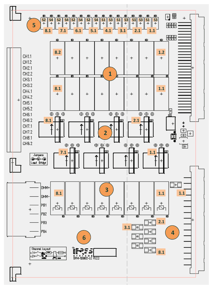
| No. | Component |
|---|---|
| 1 | load channel relays Ch. 1.1 – Ch. 8.2 |
| 2 | Shunt/LEM and channel configuration Ch. 1.1 – Ch. 8.1 |
| 3 | DMM inline relay Ch. 1.1 – Ch. 8.1 |
| 4 | Fuse 10A for Ch. 1.1 – Ch. 8.1 |
| 5 | Sense Bus relays Ch. 1.1 – Ch. 4.1 to Sense 1 and Sense 3; Ch. 5.1 – Ch. 8.1 to Sense 2 and Sense 4 |
| 6 | Serialnumber and quality check labels |
5.13Channel configuration
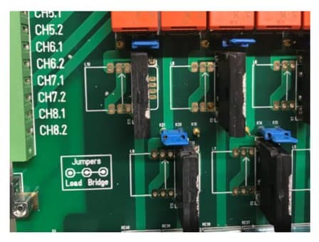
Each channel of the card can be configured via the blue jumpers to load or bridge topology:
Load: The second channel (X.2) is connected to first channel (X.1) for dual load configuration (2 loads on channel X.1)
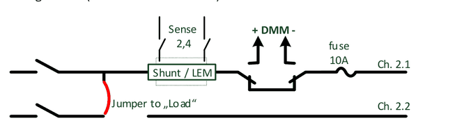
Bridge: The second channel (X.2) is bypassing first channel (X.1) for single load Configuration (X.2 channel without shunt and fuse)
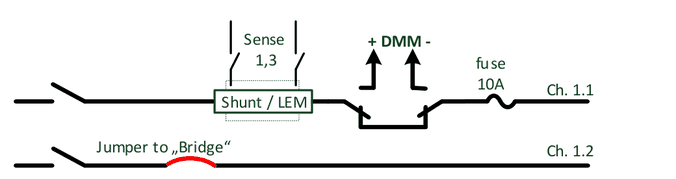
The jumper schematic is shown on the pcb: middle to left connected is “Load”, middle to right connected is “Bridge”.
5.14Connectivity
SPM-100802-LC connector X2:
| Pin | d | b | z |
|---|---|---|---|
| 2 | DMM+ | DMM+ | DMM- |
| 4 | Ch. 1.1 | Ch. 1.1 | DMM- |
| 6 | Ch. 1.2 | Ch. 1.2 | Ch. 2.1 |
| 8 | Ch. 2.2 | Ch. 2.2 | Ch. 2.1 |
| 10 | Ch. 3.1 | Ch. 3.1 | Ch. 3.2 |
| 12 | Ch. 4.1 | Ch. 4.1 | Ch. 3.2 |
| 14 | Ch. 4.2 | Ch. 4.2 | Ch. 5.1 |
| 16 | Ch. 5.2 | Ch. 5.2 | Ch. 5.1 |
| 18 | Ch. 6.1 | Ch. 6.1 | Ch. 6.2 |
| 20 | Ch. 7.1 | Ch. 7.1 | Ch. 6.2 |
| 22 | Ch. 7.2 | Ch. 7.2 | Ch. 8.1 |
| 24 | Ch. 8.2 | Ch. 8.2 | Ch. 8.1 |
| 26 | PB1 | PB1 | PB1 |
| 28 | PB2 | PB2 | PB2 |
| 30 | PB3 | PB3 | PB3 |
| 32 | PB4 | PB4 | PB4 |
X2 connector layout for cable to DUT/Adapter
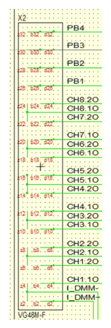
For cabling to system’s receiver interface or to DUT Adapter following data needs to be considered:
| Item | Value | Remarks |
|---|---|---|
| Max. current | 6 A | per connector pin |
| Used pins | 2 | pins used per channel and DMM |
| Used pins | 3 | pins used per Power Bus |
| Wire cross sections | AWG 16 / 1,5 mm² | per load channel wire |
| Wire cross sections | AWG 14 / 2,5 mm² | per Power Bus wire |
5.15Sparepart List
| Manufacturer / Supplier | Part Nr. | IRS Part Nr. | Component Description |
|---|---|---|---|
| Littelfuse | 0154010.DR | 118580 | Fuse 10A, SMD |
| TE Connectivity | RTD34024 | 118581 | Load channel relay 16A |
| Panasonic | AGN20024 | 105776 | Sense-Bus relay |
| Finder | 44.62.9.024.0000 | 115599 | DMM In-line relay |
| LEM | CASR 6-NP | 109760 | Optional: current transducer 6A |
| Phoenix Contact | SPC 5/ 6-STF-7,62 | 119290 | Cable side load breakout connector for power bus & DMM (for „-E“ load breakout pcb) |
| Phoenix Contact | MSTB 2,5/16-STF-5,08 | 118583 | Cable side load breakout connector for Load channels (for „-E“ load breakout pcb) |
| Isabellenhütte | PBV-R05-F1-0,5% | 112652 | Optional: Shunt 0R05, 3W, 0,5% |
5.16Product Support
- IRS Homepage: www.irs.systems
- Email Contact: info@irs.systems
Datasheet SPM-300602-LC
SPM-300602-LC – IRS products 119787 SPM-300602-LC-E, 6 Dual channels, 30A, load breakout pcb, and 120314 SPM-300602-LC-P, 6 Dual channels, 30A, load mounting panel; hardware version 1.00.
6.1General Description
The SPM-300602-LC is a high current 6HU switching module for use inside IRS Switching Platform mainframes. The module topology provides 6 dual load switching channels for max. 30A continuous current with fuse and integrated current transducers in each channel.
The module provides permanent current and temperature monitoring and allows reading of this values via API command.
Internal onboard diagnostic provides a basic functional check of each channel (relay contact, fuse, current transducer) without module removal. The module is controlled by the Switching Platform µController card SPC.
Typical tasks are load and supply switching to DUT. The module is available with a metal panel for load mounting or a breakout extension for wiring to external placed loads.
6.2Safety Instructions
- Only for use in IRS Switching Platform mainframes (e.g. SP-1200) and within the specified electrical limits.
- Use only inside suitable 19‘‘-Cabinets and not for applications to humans or animals.
- Use this SP module only with the SPC-64 µController card and with the SP-Editor SW and its API commands for configuration and control
- Hot switching is NOT recommended on any circuit of the module. This will reduce the lifetime and maximum switching cycles of the relays and possibly destroy the relays on the module.
- The module is designed for resistive loads, user has to care about protection circuitry when using inductive or capacitive loads
- Outputs need sufficient isolation and protection against contact.
6.3Schematic Overview & Pictures


6.4Scope of Delivery
SPM-300602-LC-E:
- Switching pcb completely assembled with load breakout pcb
- Frontpanel with breakout connectors and all required cable side connectors
SPM-300602-LC-P:
- Switching pcb completely assembled with metal load panel
- Frontpanel closed, no connector breakouts
6.5Certification & Compliance
| Item | Value |
|---|---|
| Certification of conformity | CE mark by IRS |
| RoHS Compliance | EU RoHS directive 2011/65/EU; Directive (EU) 2015/863 Annex II |
6.6Used Abbreviations
| Abbreviation | Meaning | Description |
|---|---|---|
| SP | Switching Platform | a general term for all Switching Platform products |
| SPB | Backplane Interface | Interface card for SP Mainframe (e.g. SP-1200) |
| SPC | Switching Platform Controller | 3HU µC card that controls a Switching Platform Module |
| SPM | Switching Platform Module | 6HU pcb with relays and other circuits controlled by a SPC-64 µController card |
| SPW | Switching Platform Wiring | standardized cable from a SPM to system interface |
| DUT | Device Under Test | same as UUT (unit under test) |
| CT | Current Transducer | inductive current measurement device |
| HU | Height Unit = 44,45 mm | |
| HP | Horizontal Pitch = 5,04 mm |
6.7Electrical
6.7.1Load Channel Specification
| Item | Value | Remarks |
|---|---|---|
| Rated Voltage | 60 Vdc | stationary |
| Rated Current / Channel | 30 A | stationary |
| Rated Current / Channel | 40 A | temporary, max. 100sec (1:2 ON/OFF ratio) |
| Switching Power (resistive load) | 10A at 60Vdc; 30A at 0-30Vdc | -> hot switching reduces lifetime ! |
| Fuse / Channel | 30A | very slow |
This values include the complete load channel incl. all components (connectors, pcb routes, fuse, current transducer, ..).
6.7.2Load Relay Specification
The current and voltage ratings of the relay are shown for information only. The “Load Channel Specification“ table shown above has to be used when creating a circuit using this module. The ratings in the “Load Channel Specification“ table are lower than the ratings for the relay by itself.
| Item | Value | Remarks |
|---|---|---|
| Max. Current | 31 A | stationary |
| Max. Voltage | 300 V | DC |
| Contact Resistance | max. 100 mOhm | initial at 1A @6Vdc |
| Switching Power (resistive load) | 10A at 60Vdc; 30A at 0-30Vdc | hot switching reduces lifetime! |
| Operating Time | max. 20ms | excl. bouncing time |
| Mechanical Life | min. 1x10^6 cycles | without el. load |
6.8Mechanical
| Item | Value | Remarks |
|---|---|---|
| Width | 6 HP | = 30,24 mm; standard width (1 slot) |
| Width | 12 HP | = 60,48 mm; double width (2 slots) |
| Height | 6 HU | = 266,7 mm |
| Depth | ~ 365 mm | total depth of card incl. front handles and rear side connectors |
| Weight | ~ 1,10 kg | for SPM-300602-LC-E incl. cable side breakout connectors |
6.9Environment
| Item | Value | Remarks |
|---|---|---|
| Operating Temperature Range | 0..55 °C; 32..131 °F | |
| Operating Humidity Range | 10-80 % | non condensing |
6.10Topology & Functions
| Item | Value | Description |
|---|---|---|
| Nr. of channels | 6 | dual load channels: 2 input channels share one common output |
| Loads / Channel | 2 | loads per channel |
| Fused Channels | 6 | all 6 channels (COM 1..6) |
| Integrated Current Measurement | yes, CT | current transducer on all 6 common lines not configurable! |
| Sense 1 connect | Ch. 1,5 | current transducers can connect to Sense Bus 1 |
| Sense 2 connect | Ch. 2,6 | current transducers can connect to Sense Bus 2 |
| Sense 3 connect | Ch. 3 | current transducers can connect to Sense Bus 3 |
| Sense 4 connect | Ch. 4 | current transducers can connect to Sense Bus 4 |
| Temperature Monitoring | yes | temperature of all load channels is measured continuously and cooling fans are activated in case of overheating |
| Current Monitoring | yes | current of all channels is continuously measured and error state (for external interlocking loop) will be set in case of exceeding the current limitation (33A) |
| Internal Diagnostic | yes, current loop | Internal diagnostic per test current routed through each channel to check fuse, current transducer and relay contact functionality; incl. report generation |
| Load Options | -P | Metal load mounting panel for internal loads |
| Load Options | -E | External load breakout pcb with clamps |
| User ID | Yes | Via SP-Editor a user defined identification string will be stored in modules EEPROM (e.g. Load ID, ..) |
| Memory Objects | Yes | Via SP-Editor memory objects can be defined and stored in modules EEPROM (e.g. calibration data, additional module information, ..); max. 6kB |
| Load Relay Cycle Counter | yes | switching cycle of each relay is counted and stored in modules EEPROM; status can be read via SW command |
| Max. Integrated Load Height | <25 mm | SPM width = 1 slot (6 HP) |
| Max. Integrated Load Height | <55 mm | SPM width = 2 slots (12 HP) |
6.11Sense Bus Measurement
6.11.1Shunts & Current Transducers in General
If SP modules provide integrated shunts or current transducers, they are an additional feature to measure the current in a load channel. This current measurement has limited precision and is not a calibrated measurement device.
If required, the user has to care about calibration and precision verification of shunts or current transducers.
6.11.2Sense Bus Topology & Data
The internal 8 wire Sense Busses 1-4 (each Sense+ and Sense-) is located on the complete backplane of the mainframe, connecting all module slots. The 4 sense busses can be connected via 4x SMB sockets on the Backplane Interface card (SPB) to external measurement devices (e.g. to measurement matrix).
On every module inside the mainframe shunts or current transducers (CT) on the load channels can be connected to the Sense Busses 1-4 by closing the corresponding sense relays on the module.
The firmware verifies that only one sense relay is connected to a sense bus at the same time. If already another channel is connected, the API switching function responds an error.
This topology allows in general 4 parallel measurements inside the SP mainframe. Not all load channels can be switched to every sense bus, possible connections are defined in the module’s datasheet.
Using multiple mainframes, the user needs to define if each of the mainframes has a separate sense bus or if they share the same sense bus. Sharing needs to be done outside of the SP mainframe by connecting all sense busses of all mainframes.
| Item | Value | Description |
|---|---|---|
| Nr. of channels | 6 | each common output (COM 1-6) for two channels has integrated current transducer |
| Sense Bus Access | 4x SMB on SPB: core: Sense +, shield: Sense - | All 8 sense bus lines can be accessed via Backplane Interface card (SPB) on 4x SMB sockets (isolated mounted) |
| Sense Bus 1 connect to | Ch. 1,5 | the sense lines of this channels can be switched to Sense-Bus #1 |
| Sense Bus 2 connect to | Ch. 2,6 | the sense lines of this channels can be switched to Sense-Bus #2 |
| Sense Bus 3 connect to | Ch. 3 | the sense lines of this channels can be switched to Sense-Bus #3 |
| Sense Bus 4 connect to | Ch. 4 | the sense lines of this channels can be switched to Sense-Bus #4 |
| Current Transducer Range | ± 51A | Range of 51A in each direction |
| Precision at 25°C (77°F) | ± 0,8% (± 0,32A) | total output error of CT module at 25°C |
| Precision at 25°C (77°F) | ± 0,40% (± 0,16A) | with autozero function after switching ON |
| Precision at 85°C (185°F) | +/- 1,50 % of Ipn; +/- 0,225A | total output error at 85°C (= max. operating temperature) |
| Sensitivity | 83,4 mV / A | output voltage range -4,25 V .. +4,25 V (+/- 51A); e.g. 1A = 83,4mV; 15A = 1,25V |
| Frequency Bandwidth | 200 kHz | +/- 1dB (1kOhm load) |
| Frequency Bandwidth | 300 kHz | +/- 3dB (1kOhm load) |
6.11.3Autozero Function
Each current transducer has an offset on the output voltage when switched supply voltage to ON This happens when switching ON the mainframe or at startup of the complete test system. This offset is constant until the current transducers supply voltage is switched OFF. This happens when switching OFF the mainframe or at shutdown of the complete test system. This offset variation is included in the total output error calculation of the current transducer’s datasheet.
A correction of this constant offset error (for the power ON phase) will improve the precision of the current transducer significant. To eliminate this offset error the SP software provides the API function “Autozero” of channels. This function also is available on the test panel of the module.
The function needs to be executed when the current is definitely “0”, means really no current is detected by the current transducer, e.g. in case the load channel is switched to open.
The recommendation is to use the autozero function minimum on each first run after system started, if it is possible execute autozero in every test sequence run.
6.12Component Location
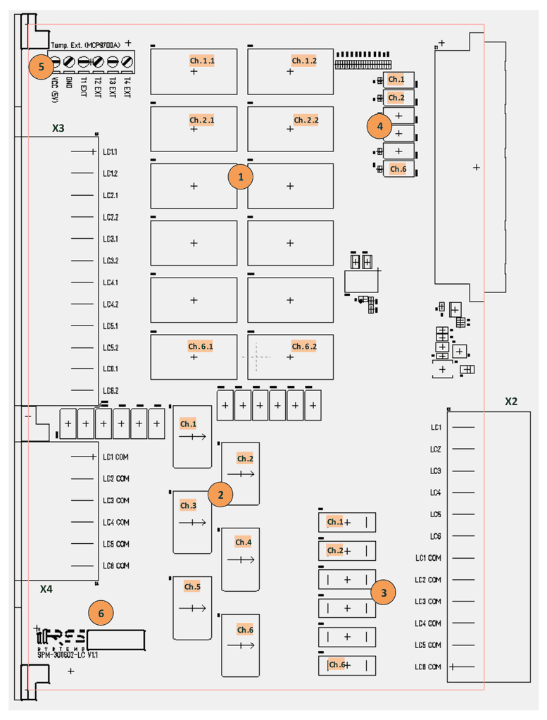
| No. | Component |
|---|---|
| 1 | load channel relays Ch. 1.1 – Ch. 6.2 |
| 2 | current transducers Ch. 1 – Ch. 6. |
| 3 | Fuse 30A for Ch. 1 – Ch. 6 |
| 4 | Sense Bus relays: Ch.1, 5 to SB1, Ch.2, 6 to SB2, Ch.3 to SB3, Ch.4 to SB4 |
| 5 | Clamps for ext. temperature sensors (MCP9700A) |
| 6 | Serialnumber and quality check labels |
6.13Connectivity
The signal names on each pin of X2, X3, X4 are labeled on the pcb. Pin 1 is always on the top of the connector.
| Pin | X2 | X3 | X4 |
|---|---|---|---|
| 1 | Ch. 1 | Ch. 1.1 | Com 1 |
| 2 | Ch. 2 | Ch. 1.2 | Com 2 |
| 3 | Ch. 3 | Ch. 2.1 | Com 3 |
| 4 | Ch. 4 | Ch. 2.2 | Com 4 |
| 5 | Ch. 5 | Ch. 3.1 | Com 5 |
| 6 | Ch. 6 | Ch. 3.2 | Com 6 |
| 7 | Com 1 | Ch. 4.1 | |
| 8 | Com 2 | Ch. 4.2 | |
| 9 | Com 3 | Ch. 5.1 | |
| 10 | Com 4 | Ch. 5.2 | |
| 11 | Com 5 | Ch. 6.1 | |
| 12 | Com 6 | Ch. 6.2 |
X2, X3, X4 connector layouts
- X2: for DUT Adapter / Fixture Interface cabling
- X3: Load side cabling, dual channels (ch. X.1, X.2)
- X4: Load side common return cabling
For cabling to system’s receiver interface, to DUT Adapter or load wiring following data needs to be considered:
| Item | Value | Remarks |
|---|---|---|
| Max. current | 41 A | per connector pin |
| Used pins | 1 | pins used per channel and com (return) line |
| Wire cross sections | AWG 12 / 4,0 mm² | per load channel and com wire for max. 30A |
| Wire cross sections | AWG 10 / 6,0 mm² | per load channel and com wire for max. 40A |
6.14SP-Editor Software
The Switching Platform Editor SW is installed on the system controller. It provides setup, configuration, information and diagnostic functions for the complete Switching Platform topology in the system.
For most functions the login level “Developer” is required. In delivery state there is no password for “Developer” defined.
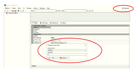
For slot- and module specific configuration and functions:
Start Switching Platform Editor SW – (1) login as developer – (2) load project configuration file or add new mainframe with autodetect – (3) connect SP mainframe – (4) select slot with module – (5) select “Slot Config” Tab and requested functional group – (6) select requested function
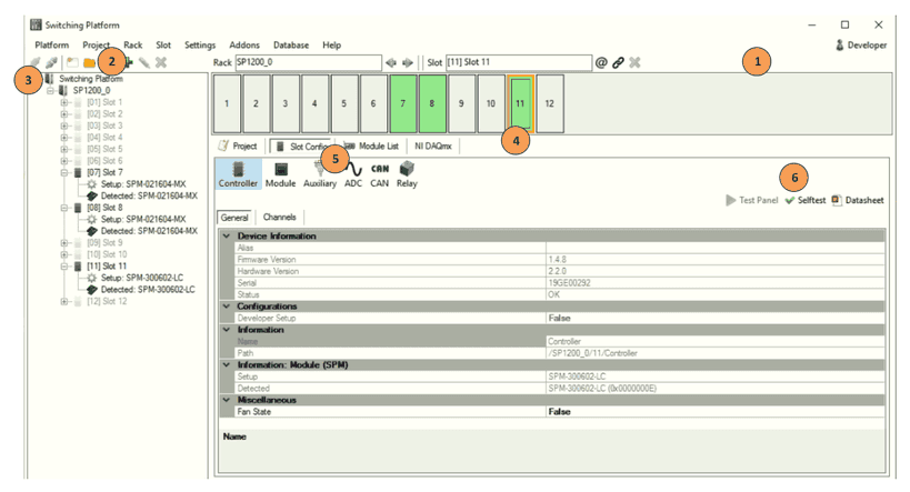
6.14.1ADC Test Panel
The SPM-300602-LC provides an ADC test panel for the module’s onboard sensors measuring pcb temperature and load path current. The current transducers constant offset can be eliminated by autozero function to improve precision. The test panel can be opened parallel to a test sequence and can be used for debugging purposes.
SP-Editor running with login as developer and loaded project configuration, SP mainframe connected – (1) select slot with SPM-300602-LC module – (2) select “Slot Config” Tab and “ADC” – (3) select “Test Panel”
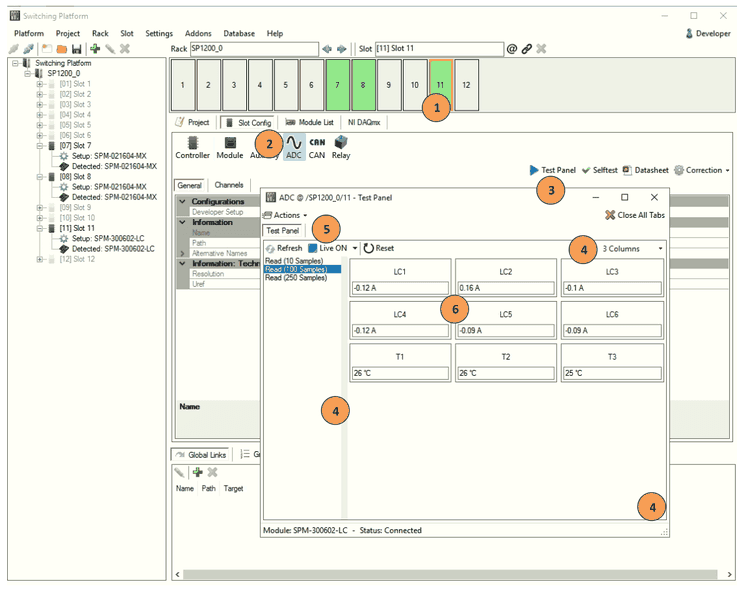
The ADC Test Panel provides temperature and load path current monitoring:
- (4) set practical size and # of columns for panel and show or hide left parameter list
- (5) Activate “Live” for monitoring values and select update rate (200ms .. 3s)
- (5) Call Action “Autozero” for resetting the current transducers permanent offset and improve current measurement precision. Note: load current needs to be “0A” to work correctly. Temperature sensors are not affected by autozero function.
- (6) Monitoring of 6x load channels current value and 3x temperature values
6.14.2Relay Test Panel
The SPM-300602-LC provides a relay test panel for two main purposes:
- manual switching of relays for debugging
- monitoring switching states parallel to automated sequences
SP-Editor running with login as developer and loaded project configuration, SP mainframe connected – (1) select slot with SPM-300602-LC module – (2) select “Slot Config” Tab and “Relay” – (3) select “Test Panel”
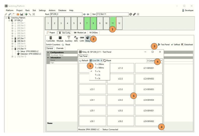
The Relay Test Panel provides monitoring and also manual switching of all accessible relays on the module:
- (4) set practical size and # of columns for panel
- (5) Activate “Live” for monitoring values and select update rate (200ms .. 3s)
- (6) Switching and monitoring of 12x load channel relays and 6x sense bus relays. Relay channels are closed/opened by clicking, closed channels are highlighted in green color
6.14.3Diagnostic & Selftest
The SPM-300602-LC provides an internal selftest sequence that verifies open and close state of load relays and functionality of fuses, current transducers and temperature sensors. After performing the selftest sequence a report is generated that can be stored by user for documentation purposes.
SP-Editor running with login as developer and loaded project configuration, SP mainframe connected – (1) select slot with SPM-300602-LC module – (2) select “Slot Config” Tab and “Relay” – (3) select “Selftest”
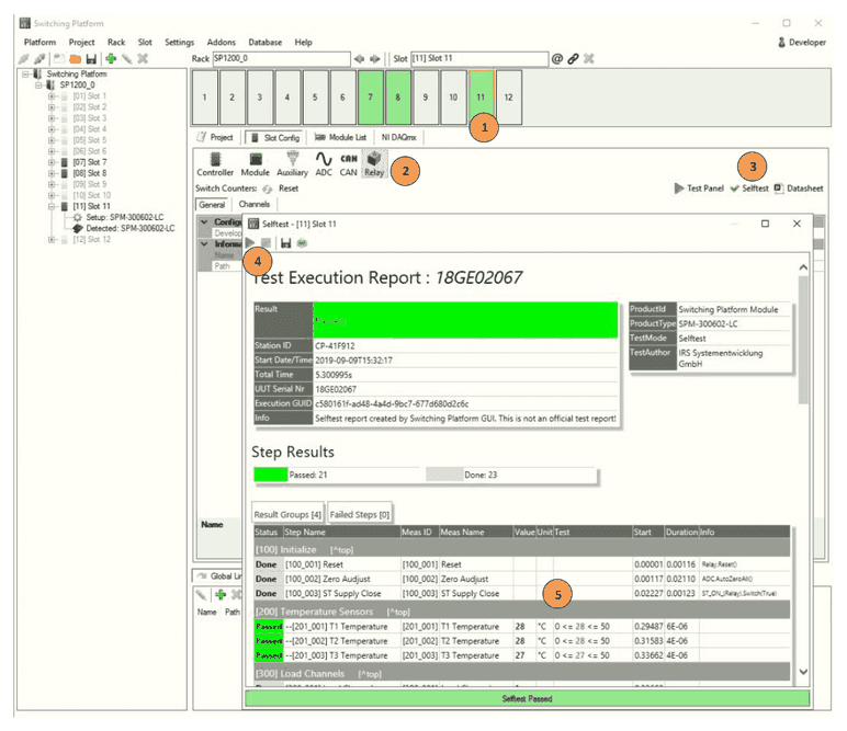
- (4) The blue arrow starts the selftest, a safety warning will be displayed before start
- (5) After execution the report is shown directly including all teststeps, results and limits. The report can be stored for documentation with the disc icon
6.14.4Equipment Protection Function
As a high current switching module, the SPM-300602-LC is continuously measuring and controlling the 6 load path currents and the 3 pcb temperature sensors. The firmware provides different protection functions when sensor values exceed defined levels.
Overtemperature Protection:
| Item | Value | Description |
|---|---|---|
| Temp. Sensor | 5 kS/s | Sample rate of temperature signal |
| Temp. Sensor | > 60 °C | Activate fan request flag for SP mainframe, 6x bottom fans are switched ON; mainframe will increase internal cooling by air stream of ~ 900 m³/hour for min. 30 seconds |
Overcurrent Protection:
| Item | Value | Description |
|---|---|---|
| Load Channel Current | 5 kS/s | Sample rate of current signal |
| Load Channel Current | > 33 A; < -33 A | Average of 1.000 samples exceeds this range: Request Error State flag for the SP mainframe. Error State relay will switch to open state and interrupt interlocking loop of power supplies or el. loads (if connected). Firmware will raise error state for complete system, each switching request will be answered with error response. Requires acknowledge of error state via SW command to reset this error state |
6.15Sparepart List
| Manufacturer / Supplier | Part Nr. | IRS Part Nr. | Component Description |
|---|---|---|---|
| Panasonic | ALFG2PF24 | 119628 | Load relay 31A |
| Panasonic | AGN20024 | 105776 | Sense-Bus relay |
| LEM | CASR 15-NP | 110327 | Current transducer 15A nominal |
| Littelfuse | 0891030.NXS | 119837 | Fuse 30A |
| Phoenix Contact | SPC 5/12-STF-7,62 | 117117 | Breakout connector 12 pin |
| Phoenix Contact | SPC 5/ 6-STF-7,62 | 119290 | Breakout connector 6 pin |
6.16Product Support
- IRS Homepage: www.irs.systems
- Email Contact: info@irs.systems
Datasheet SPM-700401-LC-MF
SPM-700401-LC-MF – IRS product 119788 SPM-700401-LC-MF-P, 4 Single channels, 70A, load mounting panel; hardware version 1.00.
7.1General Description
The SPM-700401-LC-MF is a high current 6HU switching module for use inside IRS Switching Platform mainframes. The module topology provides 4 single load switching channels for max. 70A continuous current with fuse and integrated current transducers in each channel.
The module provides permanent current and temperature monitoring and allows reading of this values via API command.
Internal onboard diagnostic provides a basic functional check of each channel (relay contact, fuse, current transducer) without module removal. The module is controlled by the Switching Platform µController card SPC.
Typical tasks are load and supply switching to DUT. The module is available with a metal panel for load mounting, custom connectors (e.g. for power supply input) can be provided on request.
7.2Safety Instructions
- Only for use in IRS Switching Platform mainframes (e.g. SP-1200) and within the specified electrical limits.
- Use only inside suitable 19‘‘-Cabinets and not for applications to humans or animals.
- Use this SP module only with the SPC-64 µController card and with the SP-Editor SW and its API commands for configuration and control
- Hot switching is NOT recommended on any circuit of the module. This will reduce the lifetime and maximum switching cycles of the relays and possibly destroy the relays on the module.
- The module is designed for resistive loads, user has to care about protection circuitry when using inductive or capacitive loads
- Outputs need sufficient isolation and protection against contact.
7.3Schematic Overview & Pictures

7.4Scope of Delivery
SPM-700401-LC-MF-P:
- Switching pcb completely assembled with blank load mounting panel
- Frontpanel closed, no connector breakouts, no load configuration*
* note: breakout connector and load configuration on request
7.5Certification & Compliance
| Item | Value |
|---|---|
| Certification of conformity | CE mark by IRS |
| RoHS Compliance | EU RoHS directive 2011/65/EU; Directive (EU) 2015/863 Annex II |
7.6Used Abbreviations
| Abbreviation | Meaning | Description |
|---|---|---|
| SP | Switching Platform | a general term for all Switching Platform products |
| SPB | Backplane Interface | Interface card for SP Mainframe (e.g. SP-1200) |
| SPC | Switching Platform Controller | 3HU µC card that controls a Switching Platform Module |
| SPM | Switching Platform Module | 6HU pcb with relays and other circuits controlled by a SPC-64 µController card |
| SPW | Switching Platform Wiring | standardized cable from a SPM to system interface |
| DUT | Device Under Test | same as UUT (unit under test) |
| CT | Current Transducer | inductive current measurement device |
| HU | Height Unit = 44,45 mm | |
| HP | Horizontal Pitch = 5,04 mm |
7.7Electrical
7.7.1Load Channel Specification
| Item | Value | Remarks |
|---|---|---|
| Rated Voltage | 60 Vdc | stationary |
| Rated Current / Channel | 70 A | stationary |
| Rated Current / Channel | 85 A | temporary, max. 60sec (1:2 ON/OFF ratio) |
| Rated Current / Channel | 100 A | temporary, max. 20sec (1:2 ON/OFF ratio) |
| VDS (reverse voltage) | max. 60 Vdc | MOSFET |
| Rds ON | max. 1 mOhm | MOSFET |
| Switching Power (resistive load) | 100 A @ <60 V | -> hot switching does not reduce lifetime of MOSFET |
| Fuse / Channel | 70 A | very slow |
This values include the complete load channel incl. all components (connectors, pcb routes, fuse, current transducer, ..).
7.7.2MOSFET Specification
The current and voltage ratings of the MOSFET are shown for information only. The “Load Channel Specification“ table shown above has to be used when creating a circuit using this module. The ratings in the “Load Channel Specification“ table are lower than the ratings for the MOSFET by itself.
| Item | Value | Remarks |
|---|---|---|
| Max. Current | 180 A | stationary |
| Max. Reverse Voltage | 60 V | DC |
| Leakage current @VGS = 0V | max. 1 µA | @VDSS=60V, Tj = 25°C |
| Leakage current @VGS = 0V | max. 100 µA | @VDSS=60V, Tj = 125°C |
| Rds ON | max. 1mOhm | MOSFET |
| Switching Power (resistive load) | 180A at <60 V | thermal cooling! |
| Contact Resistance | max. 1 mOhm | initial at 1A ID = 100 A |
| Operating Time | typ. 37 ns | VDD 30 V, Vdc 10 V, ID 100 A |
| Mechanical Life | not relevant | without el. load |
7.8Mechanical
| Item | Value | Remarks |
|---|---|---|
| Width | 6 HP | = 30,24 mm; standard width (1 slot) |
| Width | 12 HP | = 60,48 mm; double width (2 slots) |
| Height | 6 HU | = 266,7 mm |
| Depth | ~ 365 mm | total depth of card incl. front handles and rear side connectors |
| Weight | ~ 0,98 kg |
7.9Environment
| Item | Value | Remarks |
|---|---|---|
| Operating Temperature Range | 0..55 °C (32..131 °F) | |
| Operating Humidity Range | 10-80 % | non condensing |
7.10Topology & Functions
| Item | Value | Description |
|---|---|---|
| Nr. of channels | 4 | single load channels switched by MOSFET semiconductor |
| Loads / Channel | 1 | loads per channel |
| Fused Channels | 4 | all 4 channels, very slow fuse |
| Integrated Current Measurement | yes, CT | current transducer on all 4 channels, not configurable! |
| Sense 1 connect | Ch. 1 | current transducer can connect to Sense Bus 1 |
| Sense 2 connect | Ch. 2 | current transducer can connect to Sense Bus 2 |
| Sense 3 connect | Ch. 3 | current transducer can connect to Sense Bus 3 |
| Sense 4 connect | Ch. 4 | current transducer can connect to Sense Bus 4 |
| Temperature Monitoring | yes | temperature of all load channels is measured continuously and cooling fans activated in case of overheating |
| Current Monitoring | yes | current of all channels is continuously measured: error state is set and load channels MOSFET will be switched to open in case of exceeding the current limitation (100A) |
| Internal Diagnostic | yes, current loop | Internal diagnostic per test current routed through each channel to check fuse, current transducer and relay contact functionality; incl. report generation |
| Load Options | -P | Metal load mounting panel for internal loads |
| User ID | Yes | Via SP-Editor a user defined identification string will be stored in modules EEPROM (e.g. Load ID, ..) |
| Memory Objects | Yes | Via SP-Editor memory objects can be defined and stored in modules EEPROM (e.g. calibration data, additional module information, ..); max. 6kB |
| Load Relay Cycle Counter | yes | switching cycle of each relay is counted and stored in modules EEPROM; status can be read via SW command |
| Max. Integrated Load Height | <25 mm | SPM width = 1 slot (6 HP) |
| Max. Integrated Load Height | <55 mm | SPM width = 2 slots (12 HP) |
7.11Sense Bus Measurement
7.11.1Shunts & Current Transducers in General
If SP modules provide integrated shunts or current transducers, they are an additional feature to measure the current in a load channel. This current measurement has limited precision and is not a calibrated measurement device.
If required, the user has to care about calibration and precision verification of shunts or current transducers.
7.11.2Sense Bus Topology & Data
The internal 8 wire Sense Busses 1-4 (each Sense+ and Sense-) is located on the complete backplane of the mainframe, connecting all module slots. The 4 sense busses can be connected via 4x SMB sockets on the Backplane Interface card (SPB) to external measurement devices (e.g. to measurement matrix).
On every module inside the mainframe shunts or current transducers (CT) on the load channels can be connected to the Sense Busses 1-4 by closing the corresponding sense relays on the module.
The firmware verifies that only one sense relay is connected to a sense bus at the same time. If already another channel is connected, the API switching function responds an error.
This topology allows in general 4 parallel measurements inside the SP mainframe. Not all load channels can be switched to every sense bus, possible connections are defined in the module’s datasheet.
Using multiple mainframes, the user needs to define if each of the mainframes has a separate sense bus or if they share the same sense bus. Sharing needs to be done outside of the SP mainframe by connecting all sense busses of all mainframes.
| Item | Value | Description |
|---|---|---|
| Nr. of channels | 4 | each channel (Ch.1-4) has an integrated current transducer |
| Sense Bus Access | 4x SMB on SPB: core: Sense +, shield: Sense - | All 8 sense bus lines can be accessed via Backplane Interface card (SPB) on 4x SMB sockets (isolated mounted) |
| Sense Bus 1 connect to | Ch. 1 | the sense lines of this channel can be switched to Sense-Bus #1 |
| Sense Bus 2 connect to | Ch. 2 | the sense lines of this channel can be switched to Sense-Bus #2 |
| Sense Bus 3 connect to | Ch. 3 | the sense lines of this channel can be switched to Sense-Bus #3 |
| Sense Bus 4 connect to | Ch. 4 | the sense lines of this channel can be switched to Sense-Bus #4 |
| Current Transducer Range | ± 85A | Range of 85A in each direction |
| Precision at 25°C (77°F) | ± 0,8% (± 0,20A) | total output error (% of IPN) of CT module at 25°C |
| Precision at 25°C (77°F) | ± 0,4% (± 0,10A) | with autozero function after switching ON |
| Precision at 85°C (185°F) | ± 1,3% (± 0,325A) | total output error (% of IPN) at 85°C (= max. operating temperature) |
| Sensitivity | 50 mV/A | output voltage range -4,25V .. +4,25V (+/-85A); e.g. 1A = 50,0 mV; 15A = 0,75V; 85A = 4,25V |
| Frequency Bandwidth | 200 kHz | +/- 1dB (1kOhm load) |
| Frequency Bandwidth | 300 kHz | +/- 3dB (1kOhm load) |
7.11.3Autozero Function
Each current transducer has an offset on the output voltage when switched supply voltage to ON This happens when switching ON the mainframe or at startup of the complete test system. This offset is constant until the current transducers supply voltage is switched OFF. This happens when switching OFF the mainframe or at shutdown of the complete test system. This offset variation is included in the total output error calculation of the current transducer’s datasheet.
A correction of this constant offset error (for the power ON phase) will improve the precision of the current transducer significant. To eliminate this offset error the SP software provides the API function “Autozero” of channels. This function also is available on the test panel of the module.
The function needs to be executed when the current is definitely “0”, means really no current is detected by the current transducer, e.g. in case the load channel is switched to open.
The recommendation is to use the autozero function minimum on each first run after system started, if it is possible execute autozero in every test sequence run.
7.12Component Location
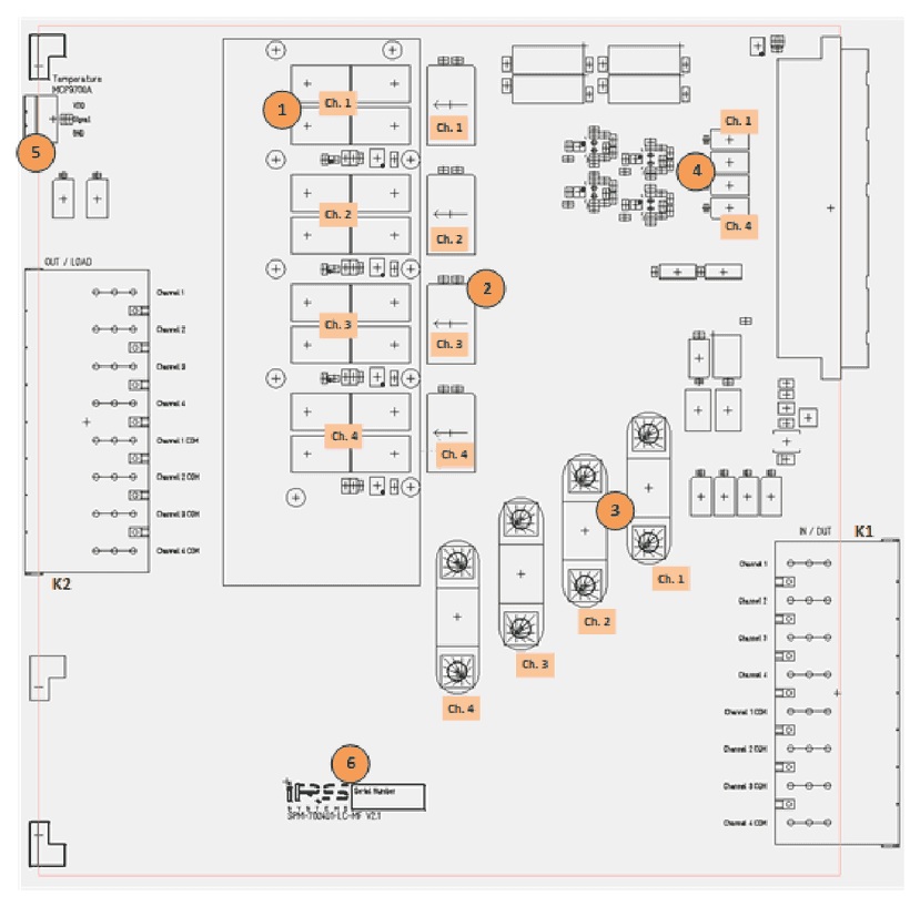
| No. | Component |
|---|---|
| 1 | load channel MOSFET Ch. 1 – Ch. 4 (below heat sink) |
| 2 | current transducers Ch. 1 – Ch. 4 |
| 3 | Fuse 70A for Ch. 1 – Ch. 4 |
| 4 | Sense Bus relays: Ch.1 to SB1, Ch.2 to SB2, Ch.3 to SB3, Ch.4 to SB4 |
| 5 | Clamps for ext. temperature sensors (MCP9700A) |
| 6 | Serialnumber and quality check labels |
7.13Connectivity
The signal names on each pin of K1, K2 are labeled on the pcb. Pin 1 is always on the top of the connector.
| Pin | K1 | K2 |
|---|---|---|
| 1 | Ch. 1 | Ch. 1 |
| 2 | Ch. 2 | Ch. 2 |
| 3 | Ch. 3 | Ch. 3 |
| 4 | Ch. 4 | Ch. 4 |
| 5 | Com 1 | Com 1 |
| 6 | Com 2 | Com 2 |
| 7 | Com 3 | Com 3 |
| 8 | Com 4 | Com 4 |
K1, K2 connector layouts
- K1: for DUT Adapter / Fixture Interface cabling
- K2: Load side cabling channels 1-4
For cabling to system’s receiver interface, to DUT Adapter or load wiring following data needs to be considered:
| Item | Value | Remarks |
|---|---|---|
| Max. current | 76 A | per connector pin |
| Used pins | 1 | pins used per channel and com (return) line |
| Wire cross sections | AWG 8 / 10,0 mm² | per load channel and com wire |
7.14SP-Editor Software
The Switching Platform Editor SW is installed on the system controller. It provides setup, configuration, information and diagnostic functions for the complete Switching Platform topology in the system.
For most functions the login level “Developer” is required. In delivery state there is no password for “Developer” defined.
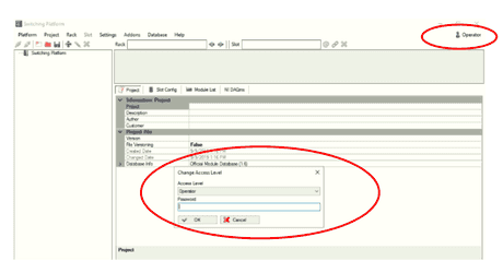
For slot- and module specific configuration and functions:
Start Switching Platform Editor SW – (1) login as developer – (2) load project configuration file or add new mainframe with autodetect – (3) connect SP mainframe – (4) select slot with module – (5) select “Slot Config” Tab and requested functional group – (6) select requested function
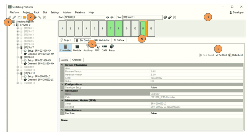
7.14.1ADC Test Panel
The SPM-700401-LC-MF provides an ADC test panel for the module’s onboard sensors measuring pcb temperature and load path current. The current transducers constant offset can be eliminated by autozero function to improve precision. The test panel can be opened parallel to a test sequence and can be used for debugging purposes.
SP-Editor running with login as developer and loaded project configuration, SP mainframe connected – (1) select slot with SPM-700401-LC-MF module – (2) select “Slot Config” Tab and “ADC” – (3) select “Test Panel”
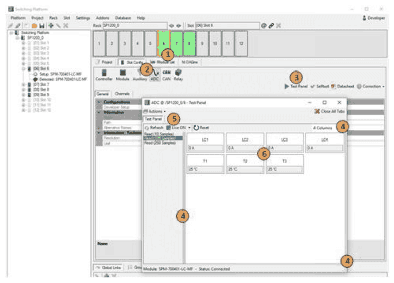
The ADC Test Panel provides temperature and load path current monitoring:
- (4) set practical size and # of columns for panel and show or hide left parameter list
- (5) Activate “Live” for monitoring values and select update rate (200ms .. 3s)
- (5) Call Action “Autozero” for resetting the current transducers permanent offset and improve current measurement precision. Note: load current needs to be “0A” to work correctly. Temperature sensors are not affected by autozero function.
- (6) Monitoring of 4x load channels current value and 3x temperature values
7.14.2Relay Test Panel
The SPM-700401-LC-MF provides a switching test panel for two main purposes:
- manual switching of relays and MOSFETs for debugging
- monitoring switching states parallel to automated sequences
SP-Editor running with login as developer and loaded project configuration, SP mainframe connected – (1) select slot with SPM-700401-LC-MF module – (2) select “Slot Config” Tab and “Relay” – (3) select “Test Panel”
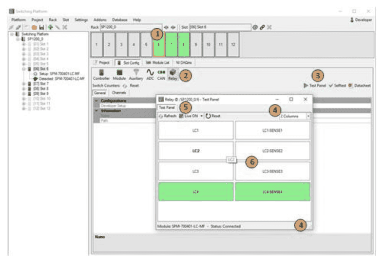
The Relay Test Panel provides monitoring and also manual switching of all accessible relays on the module:
- (4) set practical size and # of columns for panel
- (5) Activate “Live” for monitoring values and select update rate (200ms .. 3s)
- (6) Switching and monitoring of 4x load channel MOSFET and 4x sense bus relays. Relay channels are closed/opened by clicking, closed channels are highlighted in green color
7.14.3Diagnostic & Selftest
The SPM-700401-LC-MF provides an internal selftest sequence that verifies open and close state of load relays and functionality of fuses, current transducers and temperature sensors. After performing the selftest sequence a report is generated that can be stored by user for documentation purposes.
SP-Editor running with login as developer and loaded project configuration, SP mainframe connected – (1) select slot with SPM-700401-LC-MF module – (2) select “Slot Config” Tab and “Relay” – (3) select “Selftest”
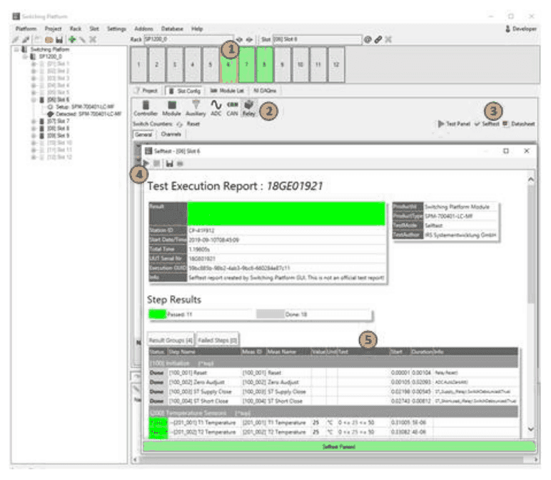
- (4) The blue arrow starts the selftest, a safety warning will be displayed before start
- (5) After execution the report is shown directly including all teststeps, results and limits. The report can be stored for documentation with the disc icon
7.14.4Equipment Protection Function
As a high current switching module, the SPM-700401-LC-MF is continuously measuring and controlling the 6 load path currents and the 3 pcb temperature sensors. The firmware provides different protection functions when sensor values exceed defined levels.
Overtemperature Protection:
| Item | Value | Description |
|---|---|---|
| Temp. Sensor | 5 kS/s | Sample rate of temperature signal |
| Temp. Sensor | > 60 °C | Activate fan request flag for SP mainframe, 6x bottom fans are switched ON; mainframe will increase internal cooling by air stream of ~ 900 m³/hour for min. 30 seconds |
Overcurrent Protection:
| Item | Value | Description |
|---|---|---|
| Load Channel Current | 5 kS/s | Sample rate of current signal |
| Load Channel Current | > 100 A; < -100 A | Average of 1.000 samples exceeds this range: 1. Load Channel will be switched to open state; 2. Request Error State flag for the SP mainframe. Error State relay will switch to open state and interrupt interlocking loop of power supplies or el. loads (if connected). Firmware will raise error state for complete system, each switching request will be answered with error response. Requires acknowledge of error state via SW command to reset this error state |
7.15Sparepart List
| Manufacturer / Supplier | Part Nr. | IRS Part Nr. | Component Description |
|---|---|---|---|
| LEM | CASR25-NP | 119072 | Current transducer with IPN = 25A |
| Littelfuse | BF1 series 70A | 118478 | Fuse 70A, very slow |
| Panasonic | AGN20024 | 105776 | Sense-Bus relay |
| Phoenix Contact | SPC 16/ 8-STF-10,16 | 107926 | Load panel connector 8 pin |
| Phoenix Contact | FMC 1,5/ 3-ST-3,81 | 109438 | Load panel connector 3 pin |
| Microchip | MCP9700A-E/TO | 118483 | Temperature Sensor Load Panel |
7.16Product Support
- IRS Homepage: www.irs.systems
- Email Contact: info@irs.systems
Switching Platform Editor
8.1Switching Platform Editor SW
- Access levels operator and developer by password (customer defined)
- Easy Configuration (drag and drop) of SP-Module population and configuration
- Auto-Setup functionality of connected and detected SP-Modules
- Definition of Alias-Names for switching channels and switching groups
- Access to modules EEPROM for custom defined specific data
- Testpanels to show switching states and ADC values and allow manual switching
- Execution of SP-Modules selftest incl. report (not all modules provide selftest)
- System settings (e.g. custom ID for SP modules)
- Project file definition for integration in Test Sequences
- 100% multithreading functionality support on Module level (threads access dedicated SP-Modules without resource sharing)
- .NET library (.NET Framework 4.6.2) and CVI wrapper function
8.2Switching Platform Startup
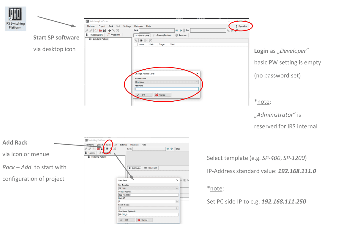
- Start SP software via desktop icon
- Login as „Developer“: basic PW setting is empty (no password set)
- Add Rack via icon or menu Rack – Add to start with configuration of project
- Select template (e.g. SP-400, SP-1200). IP-Address standard value:
192.168.111.0
8.3Database Reference
In top menu select Database – Update / Import, browse and select the *.spm database file. Then press the “open” button and confirm the update.
Verify Database version in top menu Database – Show Version.
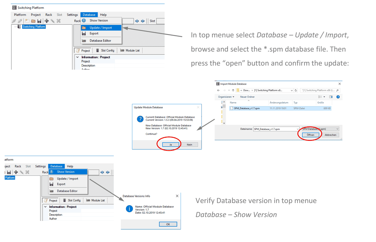
8.4SP Mainframe Population
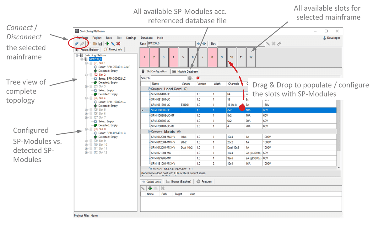
- Connect / Disconnect the selected mainframe
- Tree view of complete topology
- Configured SP-Modules vs. detected SP-Modules
- All available SP-Modules acc. referenced database file
- All available slots for selected mainframe
- Drag & Drop to populate / configure the slots with SP-Modules
8.5SP Mainframe Slot Properties
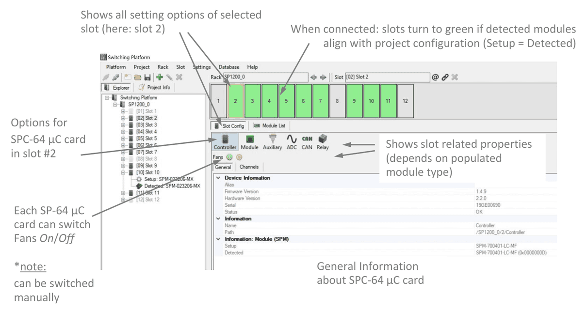
- Shows all setting options of selected slot (here: slot 2)
- When connected: slots turn to green if detected modules align with project configuration (Setup = Detected)
- Options for SPC-64 µC card in slot #2
- Shows slot related properties (depends on populated module type)
- General Information about SPC-64 µC card
- Each SP-64 µC card can switch Fans On/Off (note: can be switched manually)
8.6Auto Setup & Update Downloader
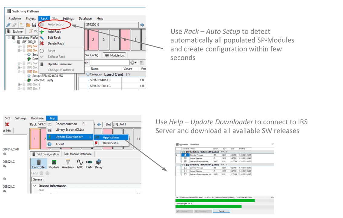
Use Rack – Auto Setup to detect automatically all populated SP-Modules and create configuration within few seconds.
Use Help – Update Downloader to connect to IRS Server and download all available SW releases.
8.7Test Panels & Selftest
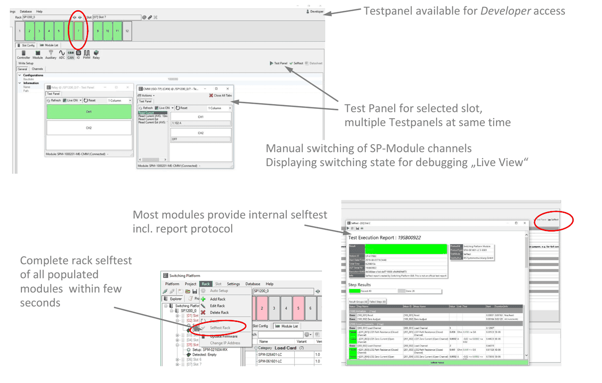
- Testpanel available for Developer access
- Test Panel for selected slot, multiple Testpanels at same time
- Manual switching of SP-Module channels
- Displaying switching state for debugging „Live View“
- Most modules provide internal selftest incl. report protocol
- Complete rack selftest of all populated modules within few seconds
8.8Project File & Configuration Report
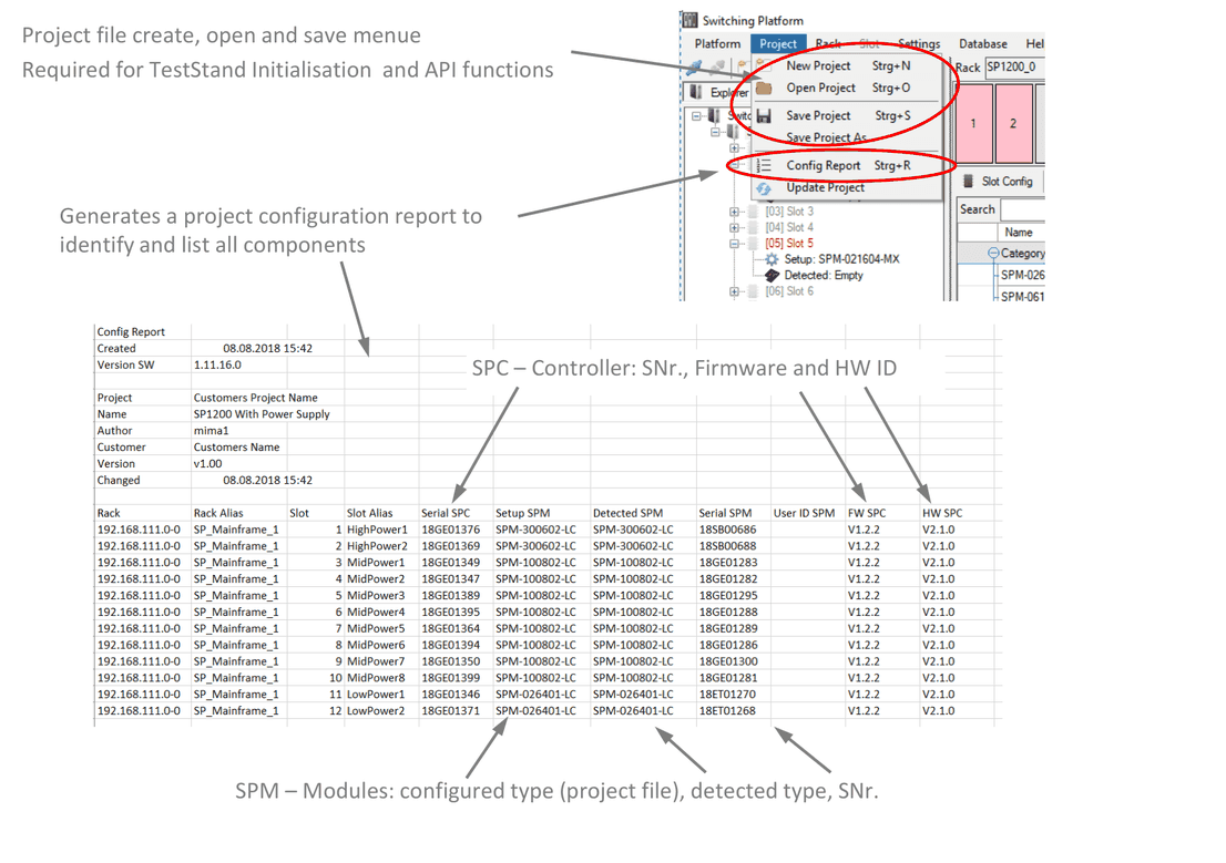
- Project file create, open and save menu: Required for TestStand Initialisation and API functions
- Generates a project configuration report to identify and list all components
- SPC – Controller: SNr., Firmware and HW ID
- SPM – Modules: configured type (project file), detected type, SNr.
8.9Request Builder
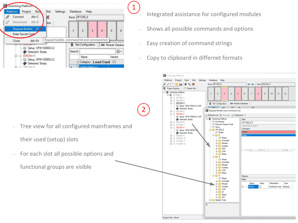
- Integrated assistance for configured modules
- Shows all possible commands and options
- Easy creation of command strings
- Copy to clipboard in different formats
- Tree view for all configured mainframes and their used (setup) slots
- For each slot all possible options and functional groups are visible
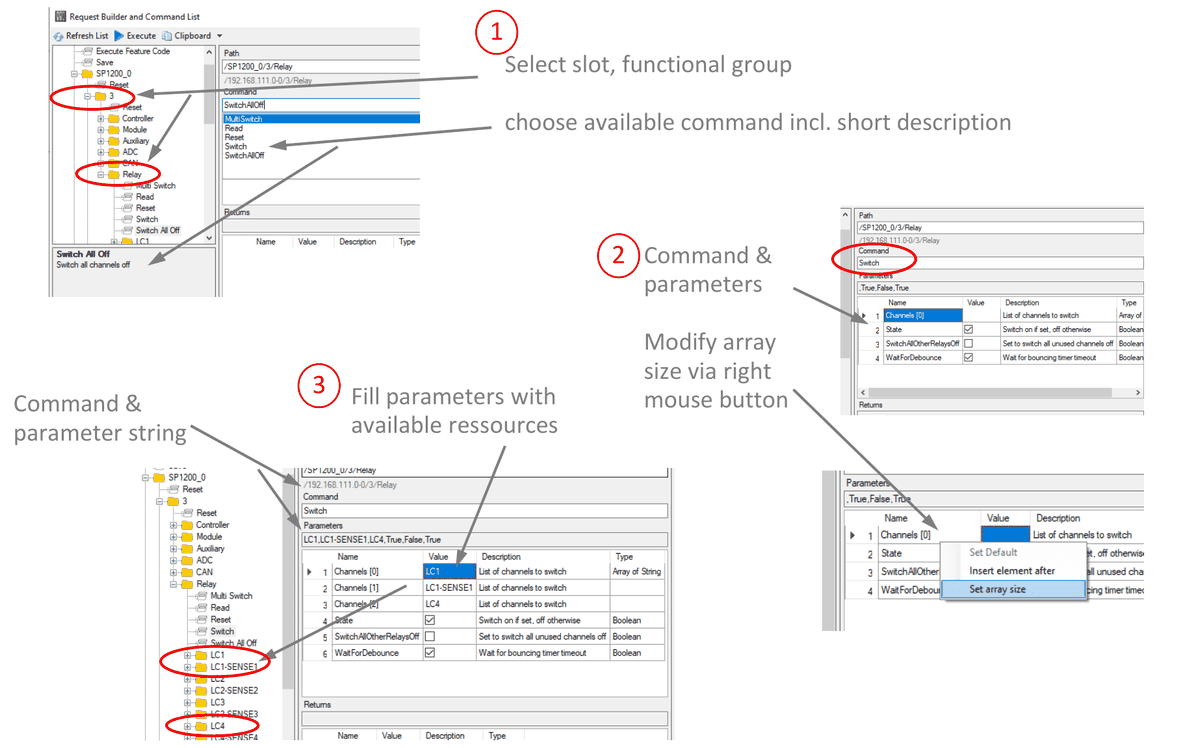
- Select slot, functional group; choose available command incl. short description
- Command & parameters; modify array size via right mouse button
- Fill parameters with available resources; command & parameter string
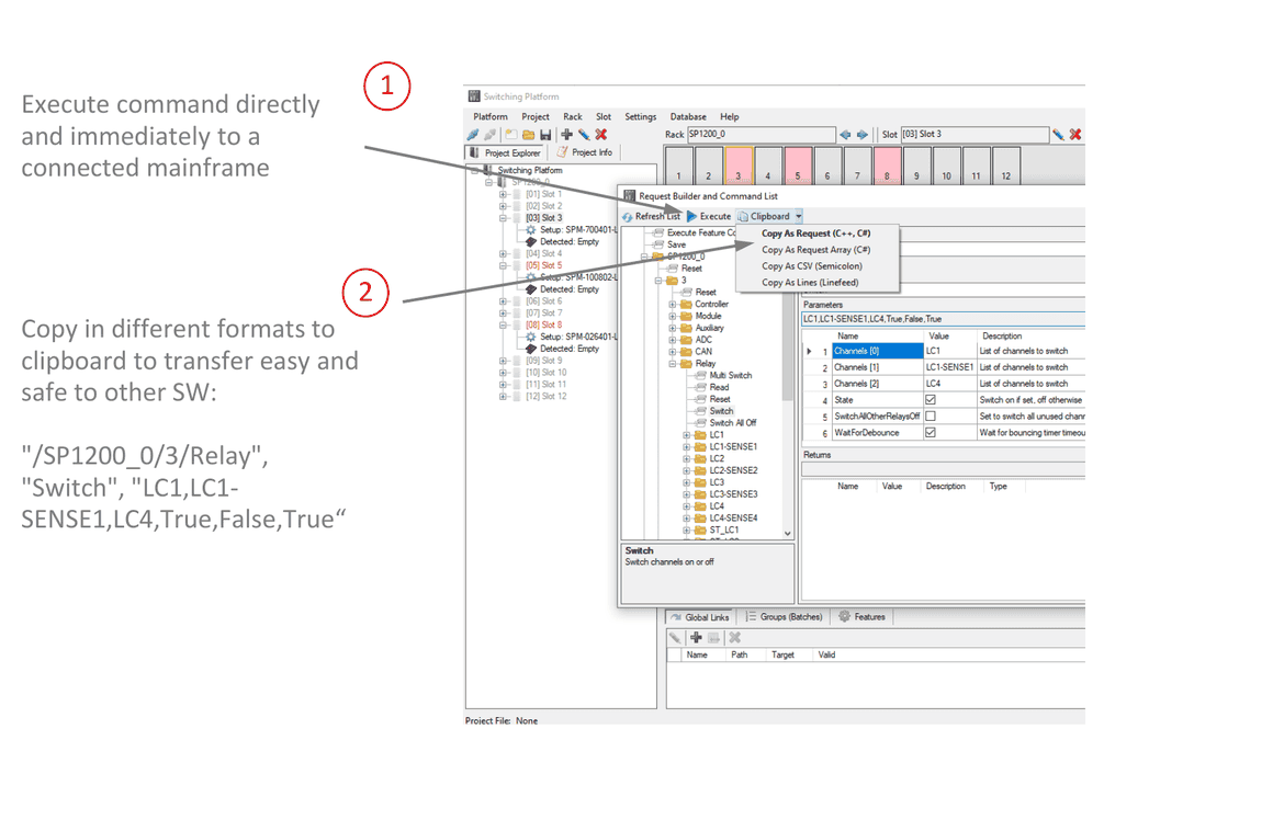
- Execute command directly and immediately to a connected mainframe
- Copy in different formats to clipboard to transfer easy and safe to other SW:
"/SP1200_0/3/Relay", "Switch", "LC1,LC1-SENSE1,LC4,True,False,True"
8.10Documentation
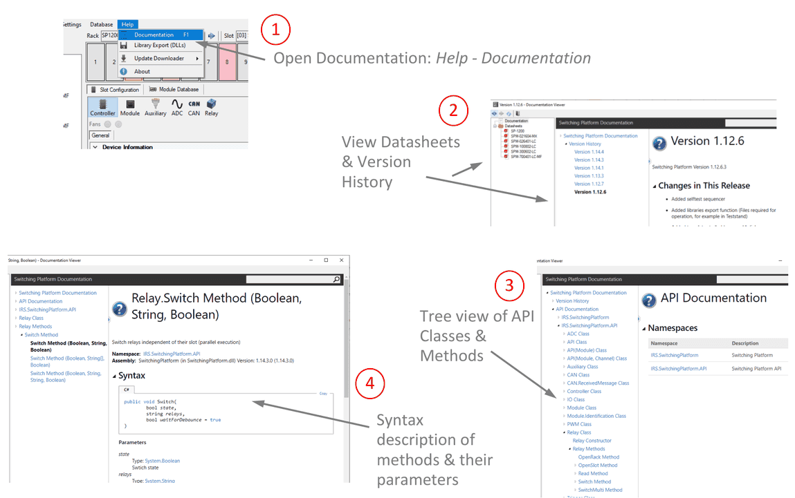
- Open Documentation: Help - Documentation
- View Datasheets & Version History
- Tree view of API Classes & Methods
- Syntax description of methods & their parameters
TestStand Integration
9.1Initialize a Switching Platform
To initialize a Switching Platform, use the dotNET Adapter and insert an action step:
- Navigate to the “
SwitchingPlatform.dll” (installation folder) - Choose the Root Class “
IRS.SwitchingPlatform.SwitchingPlatform” - Choose the .NET Invocation “
SwitchingPlatform()” (Constructor for Switching Platform Object) - Save the Object Reference in a Variable
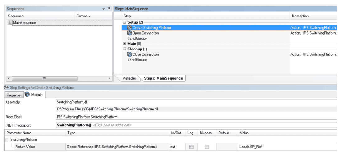
9.2Connect to SP-Mainframe / Rack
- Use the dotNET Adapter, insert an action step and navigate to the “
SwitchingPlatform.dll” - Choose the Root Class “
IRS.SwitchingPlatform.SwitchingPlatform” and the .NET Invocation “Use Existing Object(IRS.SwitchingPlatform.SwitchingPlatform).Connect(System.String, Int32)” - Refer to the Variable with the Switching Platform Object Reference
- Type in the path to your Project File (use “
\\” for path masking “C:\\TS\\Project”) - Type in Connection Timeout (recommended: “use default”)
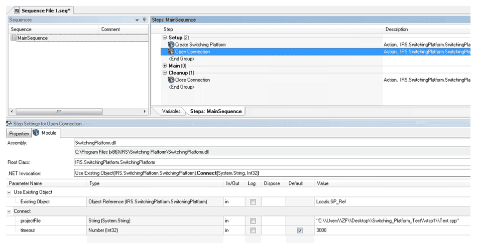
9.3Disconnect SP-Mainframe / Rack
- Use the dotNET Adapter, insert an action step and navigate to the “
SwitchingPlatform.dll” - Choose the Root Class “
IRS.SwitchingPlatform.SwitchingPlatform” and the .NET Invocation “Use Existing Object(IRS.SwitchingPlatform.SwitchingPlatform).Disconnect()” - Refer to the Variable with the Switching Platform Object Reference
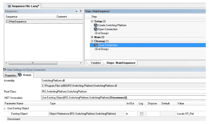
9.4Switch Relay via Request
- Use the dotNET Adapter, insert an action step and navigate to the “
SwitchingPlatform.dll” - Choose the Root Class “
IRS.SwitchingPlatform.SwitchingPlatform” and the .NET Invocation “Use Existing Object(IRS.SwitchingPlatform.SwitchingPlatform).Request(System.String, System.String, System.String)” - Refer to the Variable with the Switching Platform Object Reference
- Type in the Path to the chosen relay “
/192.168.111.0-0/2/Relay/KL30”, the command “Switch” or “Read” and the parameters
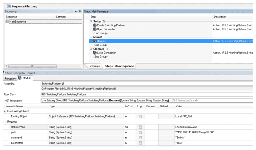
Documents and downloads
Further documents and files for your IRS product are available on myIRS.