The isolated serial interface is available in two variants, one for K-Line and one for RS485.
The interface has a galvanic isolation of min. 1kV and protects the PC Hardware from failures on the DUT side.
The K-Line is a bi-directional one wire bus mainly used in the automotive industry and specified by ISO9141 and ISO14230-1.
RS485 is a bus for differential serial data transmission and can be used over long distances and in electrically noisy environments.
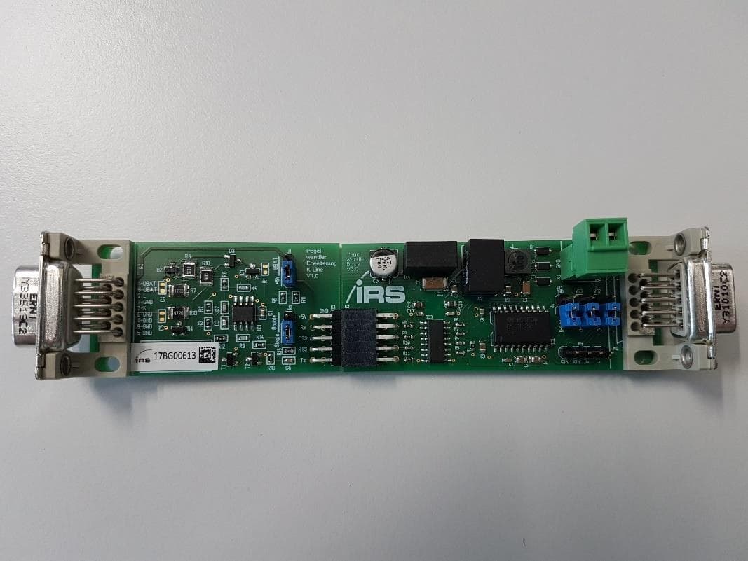
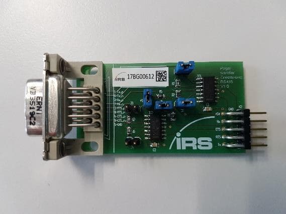
Hardware
1.1Specifications
| Parameter | Value |
|---|---|
| Supply Voltage | 6V to 24V |
| RS232 IOs | see SN65C3222 |
| K-Line IOs | 2V to 30V; 0.5A to GND |
| RS485 IOs | see SN65HVD1792D |
| Isolation | see Si8420BB and MEE1S0505SC |
| K-Line Baudrate | 200 KBaud specified by IRS but tested with up to 1.5 MBaud. See oscilloscope screenshots with 256 KBaud, 500 KBaud and 1 MBaud. |
| RS485 Baudrate | 1 MBaud specified by the RS485 Transceiver but tested with up to 3 MBaud. See oscilloscope screenshots with 1 MBaud, 2 MBaud and 3 MBaud. |
1.2Absolute maximum ratings
| Parameter | Value |
|---|---|
| Supply Voltage | -0.3V to 25V |
| RS232 IOs | see SN65C3222 |
| K-Line IOs | -0.3V to 36V (see LM2903D) |
| RS485 IOs | see SN65HVD1792D |
| Isolation | see SI8663BB and MEE1S0505SC |
Exceeding the limits might damage the device.
1.3Connectors
1.3.1Terminal block
| Pin | Function | Alternative | Direction | Comment |
|---|---|---|---|---|
| 1 | VSupply | input | 6 to 24V | |
| 2 | GNDPC |
1.3.2D-Sub9 RS232 (female)
| Pin | Function | Alternative | Direction | Comment |
|---|---|---|---|---|
| 1 | ||||
| 2 | Rx | output | Connect with Rx from PC. | |
| 3 | Tx | input | Connect with Tx from PC. | |
| 4 | VSupply (jumper) | input | 6 to 24V. Alternative for Supply Voltage if the terminal block is not used. A custom cable is needed. | |
| 5 | GNDPC | Connect with GND from PC. | ||
| 6 | DSR | output | ||
| 7 | RTS | VSupply (jumper) | input | 6 to 24V. Connect with RTS from PC. Alternative for Supply Voltage if the terminal block is not used. A custom cable is needed. |
| 8 | CTS | output | Connect with CTS from PC. | |
| 9 | GNDPC (jumper) |
1.3.3D-Sub9 K-Line / RS485 (male)
| Pin | K-Line | Direction | RS485 | Direction |
|---|---|---|---|---|
| 1 | VBat | input | Txp | output |
| 2 | L | input | Rxp | input |
| 3 | K | input/output | RTSp | output |
| 4 | GND | CTSp | input | |
| 5 | GND | GND | ||
| 6 | VBat | input | Txn | output |
| 7 | GND | Rxn | input | |
| 8 | GND | RTSn | output | |
| 9 | GND | CTSn | input |
1.4Jumper configuration
1.4.1General
It is possible to use a custom RS232 cable with wires for VSupply (Pin 4 and 7) and GNDPC (Pin 9) to supply the PCB. To be able to use the Pins on the D-Sub9, the jumpers J1, J2 and J3 have to be set.
| Jumper | Name | Comment |
|---|---|---|
| J1 | GNDPC | Pin 9 on RS232 D-Sub9 |
| J2 | VS3 | Pin 4 on RS232 D-Sub9 |
| J3 | VS2 | Pin 7 on RS232 D-Sub9. This is for backward compatibility only. Please use J2 if possible. The RTS signal is on this pin and may be used for the RS485 variant. |
1.4.2K-Line
| Jumper | Name | Comment |
|---|---|---|
| J1 | UBatt / VCC | Configuration for the pull-up voltage at the communication line. UBAT: Pull-up voltage is UBAT from the DUT. VCC: Pull-up voltage is 5V from the interface. |
| J2 | Single / Double | Configuration for single wire communication (send and receive on K-Line) or double wire communication (send on K-Line and receive on L-Line) |
1.4.3RS485
| Jumper | Name | Comment |
|---|---|---|
| J1 | 180R terminating resistor from TxP to Txn | |
| J2 | 180R terminating resistor from RxP to Rxn | |
| J3 | 180R terminating resistor from RTSP to RTSn | |
| J4 | 180R terminating resistor from CTSP to CTSn | |
| J5 | 10k resistor from RTSP to VCC | |
| J6 | 10k resistor from RTSn to GND |
1.5Order information
1.5.1PCB mounted on angle plate
- Overall dimensions: 267mm x 36mm x 18mm
| Variant | Order Number |
|---|---|
| Level Converter V5.0 variant K-Line | 118354 |
| Level Converter V5.0 variant RS485 | 118355 |
1.5.2PCB in the box
- Dimensions of the box: 150mm x 80mm x 30mm
- Overall dimensions: 154mm x 80mm x 30mm
| Variant | Order Number |
|---|---|
| Level Converter V5.0 variant K-Line | 118229 |
| Level Converter V5.0 variant RS485 | 118353 |
Signal Curves
2.1K-Line
Settings: VSupply = 12V; J4 to Single; J7 to VCC (5V); K bridged to L; transmission = 0x55


2.2RS485
Settings: VSupply = 12V; jumper on J8 and J9; Txp and Txn bridged to Rxp and Rxn; transmission = 0x55


Documents and downloads
Further documents and files for your IRS product are available on myIRS.