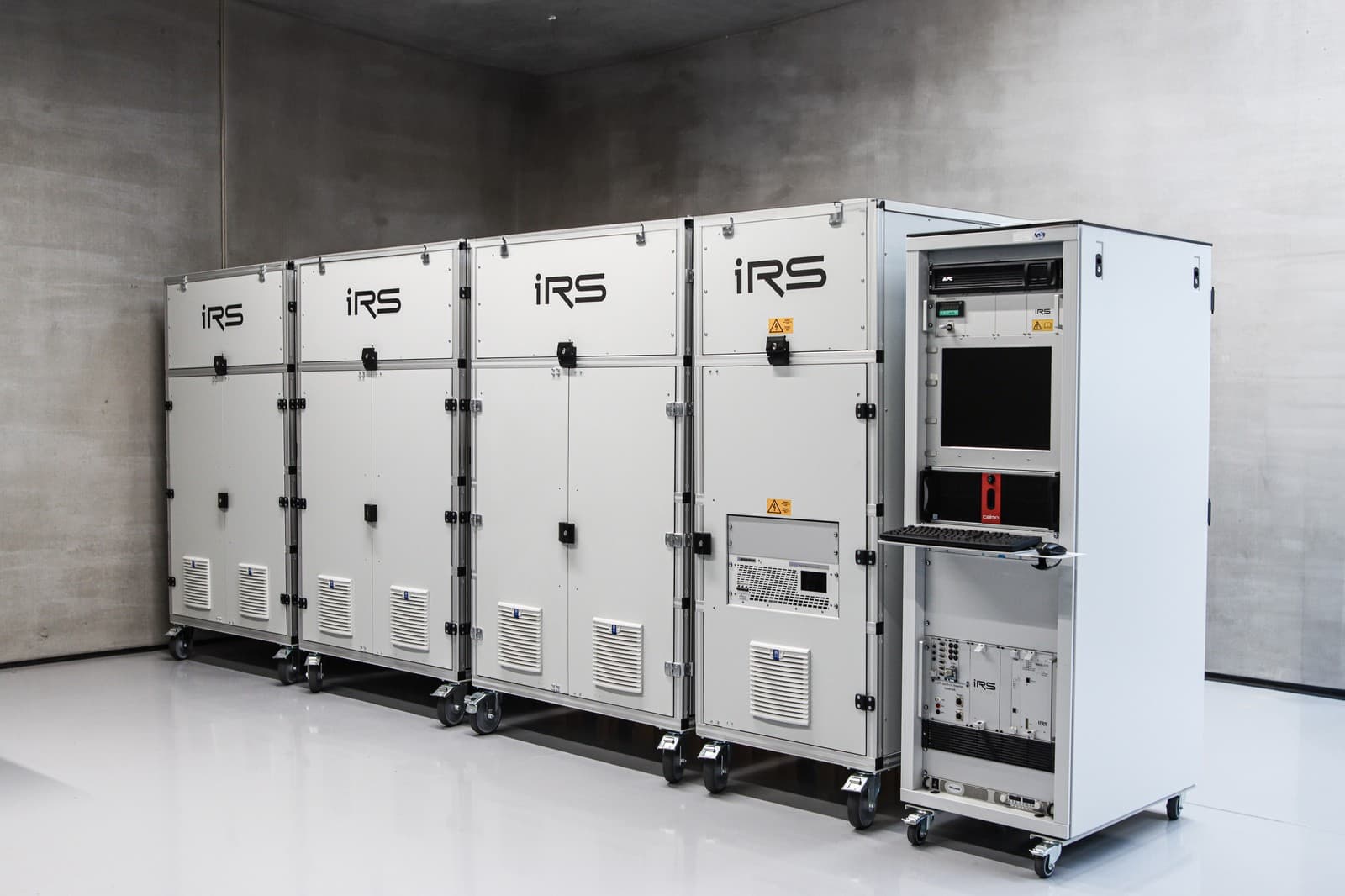
IRS SiC Roadrunner – High Power. Compact Design.
For applications with the highest power requirements, we offer the IRS SiC Roadrunner as a compact solution for SiC inverter testing.
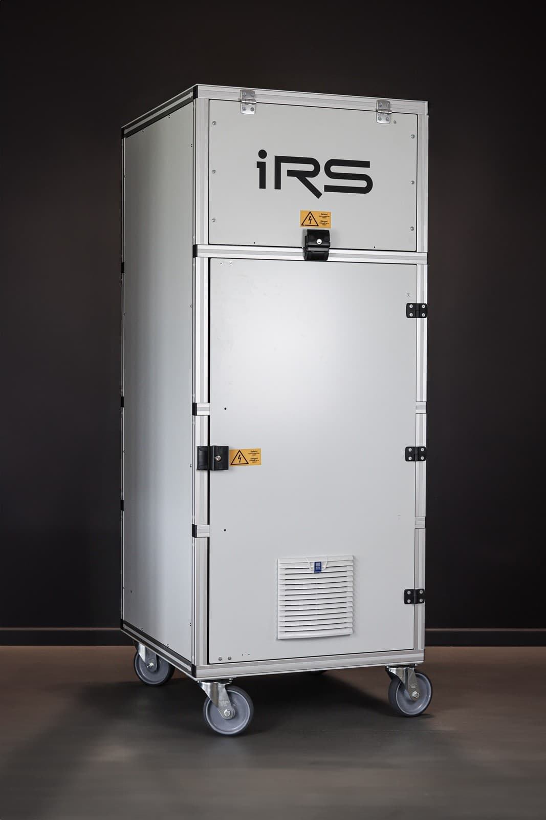
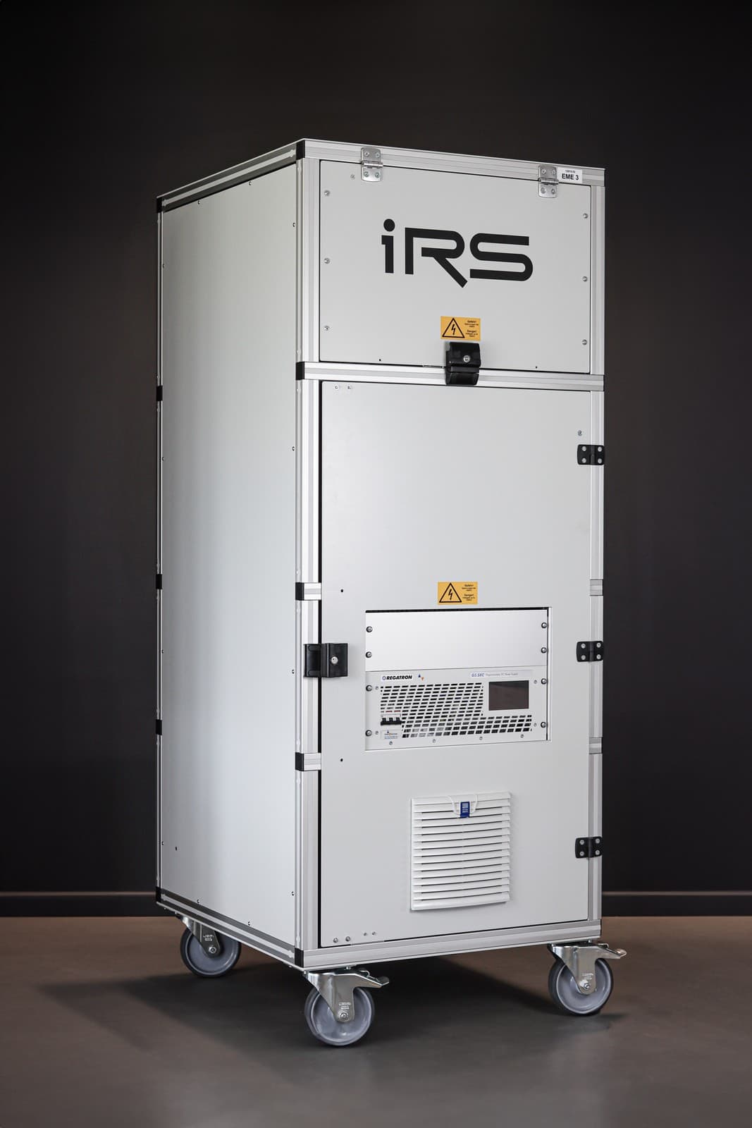
It combines the advantages of the Active Motor Load Emulator with an extremely high power density in a mobile 19" rack.
Highlights
- Efficiency up to 99%
- Frequency range up to 4 kHz (sine) and 50 kHz (switching frequency)
- Simulated active power up to 558 kW per module
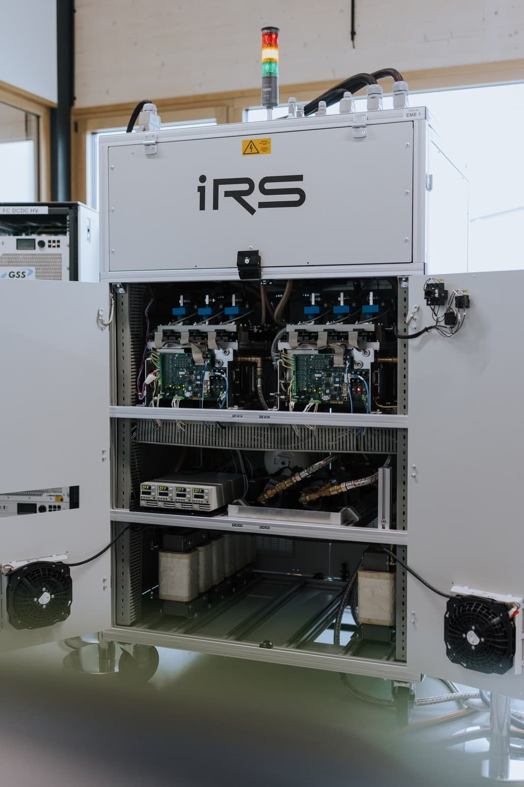
- Integrated cooling and easy integration
One of the central components of electric and hybrid vehicles is the inverter – a power electronics device that converts the direct current from the battery into alternating current for the electric motor. Testing inverters therefore requires both a battery and a motor simulation.
Battery simulations are available on the market. Depending on the parameters, either standard power supplies with or without grid feedback or complex high-power battery simulators can be used.
To simulate the motor, there are typically two options: a simple passive load with inductors or a costly high-performance electronic motor simulator.
The passive load solution is very common in all test areas in production, validation and laboratories. It is cost-effective and simple, but has the drawbacks listed in the table below. The low direct current resulting from a passive load has the advantage that relatively small power supplies can be used, but conversely the DC path of the inverter is not loaded under real conditions.
The choice of electronic motor simulators is much more limited. For high-performance inverters above 100 kW, sophisticated motor simulators are available from only a few companies at prices well above €500,000. For many applications, such as production lines or lifetime tests, the functionality of these simulators is oversized. In lifetime tests, several inverters have to be tested in parallel, which requires several motor simulations. That is why lifetime tests usually rely on the simple passive coil solution.
Properties
The concept is based on the idea of operating two inverters directly against each other – both the three motor phases and the DC link are directly coupled. A standard power supply can be used as the battery simulator. With appropriate control of the motor simulator, the phase current flows from the DUT to the simulator through the phase coils and back to the DUT via the DC link, and vice versa. This way, the DC link is loaded with a realistic current, but the energy is only exchanged between the two inverters. The battery simulation therefore only has to supply the energy for the losses of the entire system. This is one of the most important advantages: a relatively small power supply without energy feedback into the grid can be used. With a power supply of only 20 kW, motors of approx. 250 kW can be simulated. In most applications, the simulator generates the induced voltage of the motor, while the DUT operates in current control mode and defines the torque applied to the motor. Since the setup is symmetrical, either the DUT operates as a generator and the simulator as the motor load, or vice versa. This allows both standard motor operation and recuperation to be simulated. The motor simulator is used in several lifetime simulation systems, EOL testers and LV124 validation systems.
Applications
- Cost-effective motor simulator for motors in the range of 10 kW to 600 kW
- Wide voltage range of 30 V to 1000 V DC for BEV, PHEV or MHEV inverters
- Real currents at both the motor phases and the battery connection of the inverter
- Motor and recuperation operation
- Low current draw from the battery simulator
- 6-phase motor simulation available
Let's work together
Are you facing a demanding measurement or testing task? We design, develop and build the right solution together with you.