# Datasheet SPM-300602-LC
URL: https://irs.systems/en/docs/switching-platform/datasheet-spm-300602-lc
**SPM-300602-LC** – IRS products 119787 SPM-300602-LC-E, 6 Dual channels, 30A, load breakout pcb, and 120314 SPM-300602-LC-P, 6 Dual channels, 30A, load mounting panel; hardware version 1.00.
## General Description
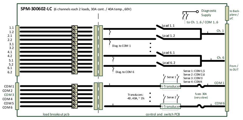
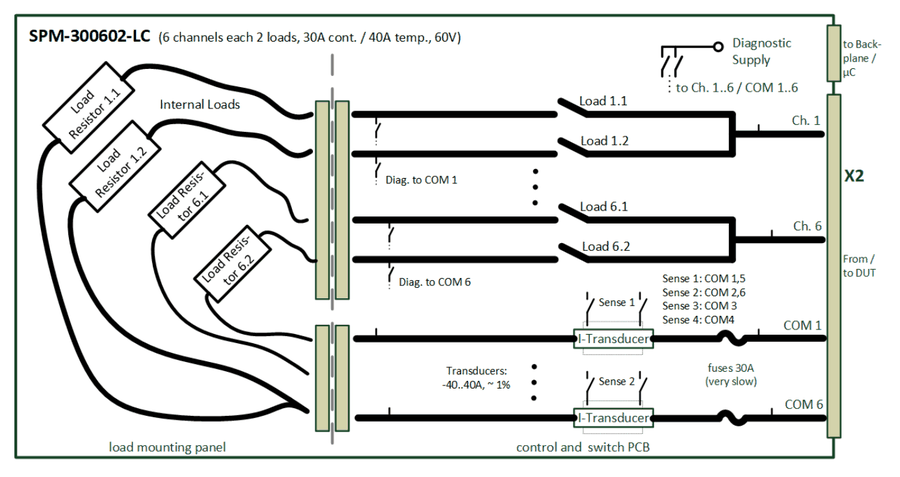
The SPM-300602-LC is a high current 6HU switching module for use inside IRS Switching Platform mainframes. The module topology provides 6 dual load switching channels for max. 30A continuous current with fuse and integrated current transducers in each channel.
The module provides permanent current and temperature monitoring and allows reading of this values via API command.
Internal onboard diagnostic provides a basic functional check of each channel (relay contact, fuse, current transducer) without module removal. The module is controlled by the Switching Platform µController card SPC.
Typical tasks are load and supply switching to DUT. The module is available with a metal panel for load mounting or a breakout extension for wiring to external placed loads.
## Safety Instructions
- Only for use in IRS Switching Platform mainframes (e.g. SP-1200) and within the specified electrical limits.
- Use only inside suitable 19‘‘-Cabinets and not for applications to humans or animals.
- Use this SP module only with the SPC-64 µController card and with the SP-Editor SW and its API commands for configuration and control
- Hot switching is NOT recommended on any circuit of the module. This will reduce the lifetime and maximum switching cycles of the relays and possibly destroy the relays on the module.
- The module is designed for resistive loads, user has to care about protection circuitry when using inductive or capacitive loads
- Outputs need sufficient isolation and protection against contact.
## Schematic Overview & Pictures
SPM-300602-LC-E (with external load breakout pcb)SPM-300602-LC-P (with metal load mounting panel)
## Scope of Delivery
SPM-300602-LC-E:
- Switching pcb completely assembled with load breakout pcb
- Frontpanel with breakout connectors and all required cable side connectors
SPM-300602-LC-P:
- Switching pcb completely assembled with metal load panel
- Frontpanel closed, no connector breakouts
## Certification & Compliance
| Item | Value |
| --- | --- |
| Certification of conformity | CE mark by IRS |
| RoHS Compliance | EU RoHS directive 2011/65/EU; Directive (EU) 2015/863 Annex II |
## Used Abbreviations
| Abbreviation | Meaning | Description |
| --- | --- | --- |
| SP | Switching Platform | a general term for all Switching Platform products |
| SPB | Backplane Interface | Interface card for SP Mainframe (e.g. SP-1200) |
| SPC | Switching Platform Controller | 3HU µC card that controls a Switching Platform Module |
| SPM | Switching Platform Module | 6HU pcb with relays and other circuits controlled by a SPC-64 µController card |
| SPW | Switching Platform Wiring | standardized cable from a SPM to system interface |
| DUT | Device Under Test | same as UUT (unit under test) |
| CT | Current Transducer | inductive current measurement device |
| HU | Height Unit = 44,45 mm | |
| HP | Horizontal Pitch = 5,04 mm | |
## Electrical
### Load Channel Specification
| Item | Value | Remarks |
| --- | --- | --- |
| Rated Voltage | 60 Vdc | stationary |
| Rated Current / Channel | 30 A | stationary |
| Rated Current / Channel | 40 A | temporary, max. 100sec (1:2 ON/OFF ratio) |
| Switching Power (resistive load) | 10A at 60Vdc; 30A at 0-30Vdc | -> hot switching reduces lifetime ! |
| Fuse / Channel | 30A | very slow |
This values include the complete load channel incl. all components (connectors, pcb routes, fuse, current transducer, ..).
### Load Relay Specification
The current and voltage ratings of the relay are shown for information only. The “Load Channel Specification“ table shown above has to be used when creating a circuit using this module. The ratings in the “Load Channel Specification“ table are lower than the ratings for the relay by itself.
| Item | Value | Remarks |
| --- | --- | --- |
| Max. Current | 31 A | stationary |
| Max. Voltage | 300 V | DC |
| Contact Resistance | max. 100 mOhm | initial at 1A @6Vdc |
| Switching Power (resistive load) | 10A at 60Vdc; 30A at 0-30Vdc | hot switching reduces lifetime! |
| Operating Time | max. 20ms | excl. bouncing time |
| Mechanical Life | min. 1x10^6 cycles | without el. load |
## Mechanical
| Item | Value | Remarks |
| --- | --- | --- |
| Width | 6 HP | = 30,24 mm; standard width (1 slot) |
| Width | 12 HP | = 60,48 mm; double width (2 slots) |
| Height | 6 HU | = 266,7 mm |
| Depth | ~ 365 mm | total depth of card incl. front handles and rear side connectors |
| Weight | ~ 1,10 kg | for SPM-300602-LC-E incl. cable side breakout connectors |
## Environment
| Item | Value | Remarks |
| --- | --- | --- |
| Operating Temperature Range | 0..55 °C; 32..131 °F | |
| Operating Humidity Range | 10-80 % | non condensing |
## Topology & Functions
| Item | Value | Description |
| --- | --- | --- |
| Nr. of channels | 6 | dual load channels: 2 input channels share one common output |
| Loads / Channel | 2 | loads per channel |
| Fused Channels | 6 | all 6 channels (COM 1..6) |
| Integrated Current Measurement | yes, CT | current transducer on all 6 common lines *not* configurable! |
| Sense 1 connect | Ch. 1,5 | current transducers can connect to Sense Bus 1 |
| Sense 2 connect | Ch. 2,6 | current transducers can connect to Sense Bus 2 |
| Sense 3 connect | Ch. 3 | current transducers can connect to Sense Bus 3 |
| Sense 4 connect | Ch. 4 | current transducers can connect to Sense Bus 4 |
| Temperature Monitoring | yes | temperature of all load channels is measured continuously and cooling fans are activated in case of overheating |
| Current Monitoring | yes | current of all channels is continuously measured and error state (for external interlocking loop) will be set in case of exceeding the current limitation (33A) |
| Internal Diagnostic | yes, current loop | Internal diagnostic per test current routed through each channel to check fuse, current transducer and relay contact functionality; incl. report generation |
| Load Options | -P | Metal load mounting panel for internal loads |
| Load Options | -E | External load breakout pcb with clamps |
| User ID | Yes | Via SP-Editor a user defined identification string will be stored in modules EEPROM (e.g. Load ID, ..) |
| Memory Objects | Yes | Via SP-Editor memory objects can be defined and stored in modules EEPROM (e.g. calibration data, additional module information, ..); max. 6kB |
| Load Relay Cycle Counter | yes | switching cycle of each relay is counted and stored in modules EEPROM; status can be read via SW command |
| Max. Integrated Load Height | <25 mm | SPM width = 1 slot (6 HP) |
| Max. Integrated Load Height | <55 mm | SPM width = 2 slots (12 HP) |
## Sense Bus Measurement
### Shunts & Current Transducers in General
If SP modules provide integrated shunts or current transducers, they are an additional feature to measure the current in a load channel. This current measurement has limited precision and is not a calibrated measurement device.
If required, the user has to care about calibration and precision verification of shunts or current transducers.
### Sense Bus Topology & Data
The internal 8 wire Sense Busses 1-4 (each Sense+ and Sense-) is located on the complete backplane of the mainframe, connecting all module slots. The 4 sense busses can be connected via 4x SMB sockets on the Backplane Interface card (SPB) to external measurement devices (e.g. to measurement matrix).
On every module inside the mainframe shunts or current transducers (CT) on the load channels can be connected to the Sense Busses 1-4 by closing the corresponding sense relays on the module.
The firmware verifies that only one sense relay is connected to a sense bus at the same time. If already another channel is connected, the API switching function responds an error.
This topology allows in general 4 parallel measurements inside the SP mainframe. Not all load channels can be switched to every sense bus, possible connections are defined in the module’s datasheet.
Using multiple mainframes, the user needs to define if each of the mainframes has a separate sense bus or if they share the same sense bus. Sharing needs to be done outside of the SP mainframe by connecting all sense busses of all mainframes.
| Item | Value | Description |
| --- | --- | --- |
| Nr. of channels | 6 | each common output (COM 1-6) for two channels has integrated current transducer |
| Sense Bus Access | 4x SMB on SPB: core: Sense +, shield: Sense - | All 8 sense bus lines can be accessed via Backplane Interface card (SPB) on 4x SMB sockets (isolated mounted) |
| Sense Bus 1 connect to | Ch. 1,5 | the sense lines of this channels can be switched to Sense-Bus #1 |
| Sense Bus 2 connect to | Ch. 2,6 | the sense lines of this channels can be switched to Sense-Bus #2 |
| Sense Bus 3 connect to | Ch. 3 | the sense lines of this channels can be switched to Sense-Bus #3 |
| Sense Bus 4 connect to | Ch. 4 | the sense lines of this channels can be switched to Sense-Bus #4 |
| Current Transducer Range | ± 51A | Range of 51A in each direction |
| Precision at 25°C (77°F) | ± 0,8% (± 0,32A) | total output error of CT module at 25°C |
| Precision at 25°C (77°F) | ± 0,40% (± 0,16A) | with autozero function after switching ON |
| Precision at 85°C (185°F) | +/- 1,50 % of Ipn; +/- 0,225A | total output error at 85°C (= max. operating temperature) |
| Sensitivity | 83,4 mV / A | output voltage range -4,25 V .. +4,25 V (+/- 51A); e.g. 1A = 83,4mV; 15A = 1,25V |
| Frequency Bandwidth | 200 kHz | +/- 1dB (1kOhm load) |
| Frequency Bandwidth | 300 kHz | +/- 3dB (1kOhm load) |
### Autozero Function
Each current transducer has an offset on the output voltage when switched supply voltage to ON This happens when switching ON the mainframe or at startup of the complete test system. This offset is constant until the current transducers supply voltage is switched OFF. This happens when switching OFF the mainframe or at shutdown of the complete test system. This offset variation is included in the total output error calculation of the current transducer’s datasheet.
A correction of this constant offset error (for the power ON phase) will improve the precision of the current transducer significant. To eliminate this offset error the SP software provides the API function “Autozero” of channels. This function also is available on the test panel of the module.
The function needs to be executed when the current is definitely “0”, means really *no* current is detected by the current transducer, e.g. in case the load channel is switched to open.
The recommendation is to use the autozero function minimum on each first run after system started, if it is possible execute autozero in every test sequence run.
## Component Location

| No. | Component |
| --- | --- |
| 1 | load channel relays Ch. 1.1 – Ch. 6.2 |
| 2 | current transducers Ch. 1 – Ch. 6. |
| 3 | Fuse 30A for Ch. 1 – Ch. 6 |
| 4 | Sense Bus relays: Ch.1, 5 to SB1, Ch.2, 6 to SB2, Ch.3 to SB3, Ch.4 to SB4 |
| 5 | Clamps for ext. temperature sensors (MCP9700A) |
| 6 | Serialnumber and quality check labels |
## Connectivity
The signal names on each pin of X2, X3, X4 are labeled on the pcb. Pin 1 is always on the top of the connector.
| Pin | X2 | X3 | X4 |
| --- | --- | --- | --- |
| 1 | Ch. 1 | Ch. 1.1 | Com 1 |
| 2 | Ch. 2 | Ch. 1.2 | Com 2 |
| 3 | Ch. 3 | Ch. 2.1 | Com 3 |
| 4 | Ch. 4 | Ch. 2.2 | Com 4 |
| 5 | Ch. 5 | Ch. 3.1 | Com 5 |
| 6 | Ch. 6 | Ch. 3.2 | Com 6 |
| 7 | Com 1 | Ch. 4.1 | |
| 8 | Com 2 | Ch. 4.2 | |
| 9 | Com 3 | Ch. 5.1 | |
| 10 | Com 4 | Ch. 5.2 | |
| 11 | Com 5 | Ch. 6.1 | |
| 12 | Com 6 | Ch. 6.2 | |
*X2, X3, X4 connector layouts*
- X2: for DUT Adapter / Fixture Interface cabling
- X3: Load side cabling, dual channels (ch. X.1, X.2)
- X4: Load side common return cabling
For cabling to system’s receiver interface, to DUT Adapter or load wiring following data needs to be considered:
| Item | Value | Remarks |
| --- | --- | --- |
| Max. current | 41 A | per connector pin |
| Used pins | 1 | pins used per channel and com (return) line |
| Wire cross sections | AWG 12 / 4,0 mm² | per load channel and com wire for max. 30A |
| Wire cross sections | AWG 10 / 6,0 mm² | per load channel and com wire for max. 40A |
## SP-Editor Software
The Switching Platform Editor SW is installed on the system controller. It provides setup, configuration, information and diagnostic functions for the complete Switching Platform topology in the system.
For most functions the login level “Developer” is required. In delivery state there is no password for “Developer” defined.

For slot- and module specific configuration and functions:
*Start Switching Platform Editor SW – (1) login as developer – (2) load project configuration file or add new mainframe with autodetect – (3) connect SP mainframe – (4) select slot with module – (5) select “Slot Config” Tab and requested functional group – (6) select requested function*

### ADC Test Panel
The SPM-300602-LC provides an ADC test panel for the module’s onboard sensors measuring pcb temperature and load path current. The current transducers constant offset can be eliminated by autozero function to improve precision. The test panel can be opened parallel to a test sequence and can be used for debugging purposes.
*SP-Editor running with login as developer and loaded project configuration, SP mainframe connected – (1) select slot with SPM-300602-LC module – (2) select “Slot Config” Tab and “ADC” – (3) select “Test Panel”*

The ADC Test Panel provides temperature and load path current monitoring:
- (4) set practical size and # of columns for panel and show or hide left parameter list
- (5) Activate “Live” for monitoring values and select update rate (200ms .. 3s)
- (5) Call Action “Autozero” for resetting the current transducers permanent offset and improve current measurement precision. Note: load current needs to be “0A” to work correctly. Temperature sensors are *not* affected by autozero function.
- (6) Monitoring of 6x load channels current value and 3x temperature values
### Relay Test Panel
The SPM-300602-LC provides a relay test panel for two main purposes:
- manual switching of relays for debugging
- monitoring switching states parallel to automated sequences
> **Warning**
> Manual switching can cause shorts and damage the modules pcb, components and cabling. Operator is responsible for switching safety. Damage caused by manual switching are not covered by warranty.
*SP-Editor running with login as developer and loaded project configuration, SP mainframe connected – (1) select slot with SPM-300602-LC module – (2) select “Slot Config” Tab and “Relay” – (3) select “Test Panel”*

The Relay Test Panel provides monitoring and also manual switching of all accessible relays on the module:
- (4) set practical size and # of columns for panel
- (5) Activate “Live” for monitoring values and select update rate (200ms .. 3s)
- (6) Switching and monitoring of 12x load channel relays and 6x sense bus relays. Relay channels are closed/opened by clicking, closed channels are highlighted in green color
### Diagnostic & Selftest
The SPM-300602-LC provides an internal selftest sequence that verifies open and close state of load relays and functionality of fuses, current transducers and temperature sensors. After performing the selftest sequence a report is generated that can be stored by user for documentation purposes.
*SP-Editor running with login as developer and loaded project configuration, SP mainframe connected – (1) select slot with SPM-300602-LC module – (2) select “Slot Config” Tab and “Relay” – (3) select “Selftest”*

> **Warning**
> Selftest creates shorts on the modules load circuits load side and DUT side. Any applied voltage or other active signals on the load and DUT side will cause damage to the module: Disconnect DUT side or/and system interface to test adapter (e.g. ITA). Disable or/and disconnect any active load side devices (e.g. power supplies).
- (4) The blue arrow starts the selftest, a safety warning will be displayed before start
- (5) After execution the report is shown directly including all teststeps, results and limits. The report can be stored for documentation with the disc icon
### Equipment Protection Function
As a high current switching module, the SPM-300602-LC is continuously measuring and controlling the 6 load path currents and the 3 pcb temperature sensors. The firmware provides different protection functions when sensor values exceed defined levels.
Overtemperature Protection:
| Item | Value | Description |
| --- | --- | --- |
| Temp. Sensor | 5 kS/s | Sample rate of temperature signal |
| Temp. Sensor | > 60 °C | Activate fan request flag for SP mainframe, 6x bottom fans are switched ON; mainframe will increase internal cooling by air stream of ~ 900 m³/hour for min. 30 seconds |
Overcurrent Protection:
| Item | Value | Description |
| --- | --- | --- |
| Load Channel Current | 5 kS/s | Sample rate of current signal |
| Load Channel Current | > 33 A; < -33 A | Average of 1.000 samples exceeds this range: Request Error State flag for the SP mainframe. Error State relay will switch to open state and interrupt interlocking loop of power supplies or el. loads (if connected). Firmware will raise error state for complete system, each switching request will be answered with error response. Requires acknowledge of error state via SW command to reset this error state |
## Sparepart List
| Manufacturer / Supplier | Part Nr. | IRS Part Nr. | Component Description |
| --- | --- | --- | --- |
| Panasonic | ALFG2PF24 | `119628` | Load relay 31A |
| Panasonic | AGN20024 | `105776` | Sense-Bus relay |
| LEM | CASR 15-NP | `110327` | Current transducer 15A nominal |
| Littelfuse | 0891030.NXS | `119837` | Fuse 30A |
| Phoenix Contact | SPC 5/12-STF-7,62 | `117117` | Breakout connector 12 pin |
| Phoenix Contact | SPC 5/ 6-STF-7,62 | `119290` | Breakout connector 6 pin |
## Product Support
- IRS Homepage: [www.irs.systems](https://www.irs.systems/)
- Email Contact: info@irs.systems