# Wiring Examples
URL: https://irs.systems/en/docs/discharge-unit-ssr/wiring-examples
The following examples illustrate typical applications. Dashed connections are optional. Fuse protection, conductor protection, and the sizing of the discharge resistor must be adapted to the specific application. The discharge resistor can be dimensioned in accordance with Chapter [5.3](/en/docs/discharge-unit-ssr/wiring-examples#discharge-time-and-energy-sizing).
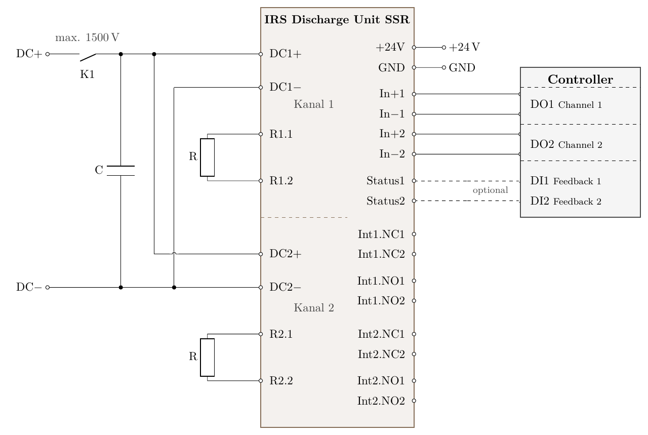
## Redundant Discharge
Both channels are connected to the same DC-link, each using its own discharge resistor.
Figure 3: Redundant discharge of a DC-link
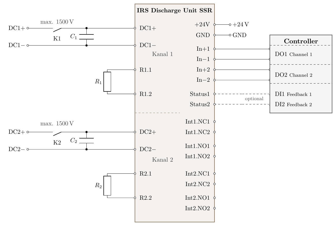
## Two separate DC-links
Each channel discharges a separate DC-link.
Figure 4: Discharge zwo separate DC-links
## Discharge Time and Energy Sizing
The time until the voltage Ures has decreased to
$$
t = R C \cdot \ln\left(\frac{U_0}{U_{res}}\right)
$$
The discharge resistor must be rated for the maximum pulse power occurring during discharge
$$
P_i = \frac{U^2}{R}
$$
If discharge occurs at intervals of T[s], the resistor must be rated for a continuous power of at least
$$
P=\frac{C\cdot U^2}{2\cdot T}
$$
Several example values are shown in Table [1](/en/docs/discharge-unit-ssr/wiring-examples#discharge-time-and-energy-sizing)
**Table 1: Example Values for R = 100 Ω, U0 = 1500 V, Ures = 60 V, T = 120 s**
| Capacitance C | t [ms] | Pi[kW] | P[W] |
| ---: | ---: | ---: | ---: |
| 100 µF | 32 | 22.5 | 1 |
| 1 mF | 322 | 22.5 | 10 |
| 10 mF (max.) | 3300 | 22.5 | 100 |